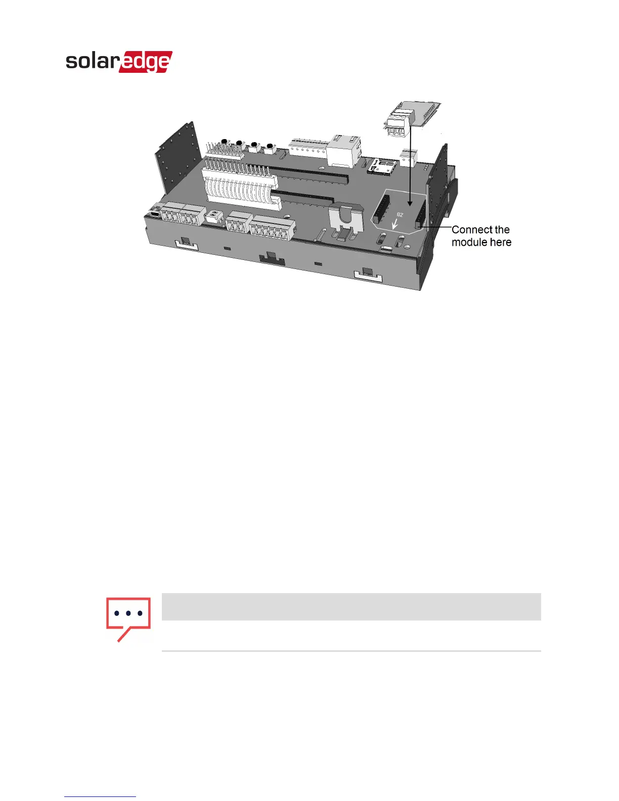
Figure 10: Connecting the module to the Commercial Gateway
4. Loosen the screws of pins A(+), B(-), and G on the RS485 3-
pin terminal block.
5. Insert the wire ends into the G, A and B pins shown above.
Use Four- or six-wire twisted pair cable for this connection.
You can use any color wire for each of the A, B and G
connections, as long as the same color wire is used for all A
pins, the same color for all B pins and the same color for all
G pins.
6.
For creating an RS485 bus - connect all B, A and G pins in
all devices.
NOTE
Do not cross-connect B, A and G wires.
7.
Terminate the first and last device in the chain by switching
a termination DIP switch to ON:
RS485 Expansion Kit Installation Guide MAN-01-00258-1.0
Chapter 2: Installation 16