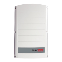
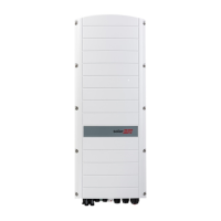
How to fix String voltage is 0V on SolarEdge Inverter?
- RRobert AtkinsonSep 7, 2025
If the string voltage is 0V on your SolarEdge Inverter, it means a power optimizer output is disconnected. To fix this, connect all power optimizer outputs.
How to fix String voltage is 0V on SolarEdge Inverter?
If the string voltage is 0V on your SolarEdge Inverter, it means a power optimizer output is disconnected. To fix this, connect all power optimizer outputs.
What to do if G Server Ping Failed on SolarEdge Inverter?
If your SolarEdge Inverter displays 'G Server Ping Failed', it indicates that the ping to google.com has failed. To resolve this, connect a laptop and check for internet connectivity.
What to do if SolarEdge SE12.5k Inverter string voltage is not 0V but lower than number of optimizers?
If the string voltage on your SolarEdge Inverter is not 0V but lower than the number of optimizers, it could be due to: * Power optimizers not connected in the string. Connect all power optimizers. * Modules not connected properly to power optimizer inputs (not applicable to smart modules). Connect the modules to the optimizer inputs. * String reverse polarity. Check the string polarity using a voltmeter and correct if needed.
How to fix SolarEdge SE12.5k Inverter no DHCP?
If your SolarEdge Inverter shows 'No DHCP', it could be due to an IP settings issue. Check both the router and the inverter configuration. You may need to configure a static IP address or set the inverter to DHCP. Consult your network IT professional for assistance.
What to do if SolarEdge Inverter string voltage is 0V?
If the string voltage on your SolarEdge Inverter is 0V, it is likely that one or more power optimizer outputs are disconnected. Ensure that all power optimizer outputs are properly connected.
How to fix SolarEdge SE12.5k LAN cable disconnected?
If your SolarEdge Inverter displays a 'LAN cable disconnected' error, it indicates a physical connection fault. Check the cable pin-out assignment and the cable connection itself.
Details critical warnings for safe operation and installation.
Alerts users to the risk of electric shock from stored energy.
Emphasizes proper grounding of the inverter and AC power cable.
States that only qualified personnel should perform repairs or testing.
Details SafeDC voltage compliance requirements with IEC60947-3.
Details safety warnings and cautions specific to power optimizer installation.
Details determining the mounting location and using brackets.
Explains how to connect the module's positive output to the optimizer's positive input.
Explains how to connect the module's negative output to the optimizer's negative input.
Discusses constructing parallel strings and string length specifications.
Details how to connect multiple power optimizers sequentially in a string.
Explains the expected voltage output from connected optimizers.
Guides on measuring string voltage and verifying correct polarity.
Ensures the mounting surface supports the inverter and bracket securely.
Reiterates cautions for handling heavy inverters to prevent injury.
Recommends mounting location protected from direct sunlight.
Details minimum clearance requirements for heat dissipation around the inverter.
Specifies clearance between multiple inverters installed side-by-side or stacked.
Guides on positioning the bracket and marking drill hole locations.
Instructions for drilling holes and securely attaching the mounting bracket.
Steps for safely hanging the inverter onto the installed mounting bracket.
Instructions for securing the Connection Unit bracket to the wall.
Describes inserting screws to secure the inverter to the bracket.
Provides guidelines for connecting the inverter to the AC grid.
Specifies the five-wire cable and maximum wire size for AC connection.
Steps for turning off AC breaker and removing the inverter cover.
Specifies the order of connecting AC wires (PE first) and terminals.
How to connect DC strings to the inverter's DC+ and DC- connectors.
Guides on activating the system using the activation card.
How to check the inverter's status after activation, including country settings.
Steps for turning on the DC Safety Unit after configuration.
Explains the need for pairing and when to perform it.
Details pressing and holding the LCD Light button to start pairing.
Shows the message displayed upon successful pairing completion.
Warns about high DC voltage when the ON/OFF switch is turned ON.
Guides on verifying LED status and LCD panel readings after activation.
Cautions regarding connecting cables and configuring parameters.
How to connect the inverter to the monitoring platform via Ethernet.
Step-by-step guide to connect the Ethernet cable through the gland.
Instructions for crimping and connecting the RJ45 connector to the communication board.
Connecting the RJ45 connector to the Ethernet switch or router.
Steps to configure the inverter for LAN connection.
Describes creating a bus of connected inverters via RS485.
Cable type, wire cross-section, max nodes, and distance for RS485.
Shows how inverters are connected in a chain via RS485.
Details inserting wires into G, A, and B pins on the RS485 terminal block.
How to use DIP-switches to terminate the first and last devices in the RS485 chain.
Designating a master inverter and connecting it to the monitoring platform.
Steps to configure the RS485 bus, setting master/slave roles.
Configuring the inverter as master via LCD menus.
Checking the master inverter's connection to the monitoring platform.
Steps to close the cover and turn ON AC and DC Safety Unit.
Verifying connection success on the inverter LCD panel (S_OK indicator).
Explains that S_OK indicates a successful connection to the monitoring platform.
Guides on identifying and resolving Ethernet communication errors.
Lists Ethernet error messages and their causes/troubleshooting steps.
Troubleshooting steps for "Master Not Found" and missing slaves in RS485.
Causes and solutions for pairing failures, including shaded optimizers.
Troubleshooting for zero or low string voltage based on optimizer connection.
Warning about high voltage and its impact on safe low voltage operation.
Steps to disconnect wires, measure optimizer voltage, and locate faults.
Lists components of the DC Safety Unit: switch, surge protector, fuses.
Steps to turn OFF inverter, AC breaker, and DC Safety Unit.
Instructions for opening the DC Safety Unit cover.
Connecting the grounding wire to the equipment grounding terminal.
Connecting AC wires to inverter terminal blocks according to labels.
Connecting DC wires to spring-clamp terminals without fuses.
Fastening screws for DC terminals with fuses.
Securing the DC Safety Unit cover with specified torque.
Explains how DC voltage drops to safe levels when AC is OFF.
Describes the mechanism operation when ON/OFF switch or AC breaker is turned OFF.
Step-by-step guide for replacing the inverter.
Disconnecting AC, DC, and RS485 wires from the inverter.
Steps to remove screws and detach the inverter from its mounting bracket.
Procedure for removing and installing a new DC Safety Unit.
| Power Output | 12.5 kW |
|---|---|
| Rated AC Power | 12.5 kW |
| AC Voltage | 208/240 V |
| Maximum Efficiency | 98.3% |
| Number of MPP Trackers | 2 |
| Warranty | 12 years |
| Max. AC Power | 12.5 kW |
| Cooling | Convection |
| Communication | Ethernet, RS485 |
| Operating Temperature Range | -25 to +60 °C |
| Model | SolarEdge SE12.5k |


