EasyManua.ls Logo

SolarEdge SE120K User Manual

SolarEdge SE120K
105 pages
To Next Page IconTo Next Page
Page #1 background imageLoading...
Page #1 background image
Installation Guide
Three Phase Inverters with
Synergy Technology
with SetApp Configuration
PN: SExxK-xxxxIxxxx
For North America
Version 1.3

Table of Contents

Question and Answer IconNeed help?

Do you have a question about the SolarEdge SE120K and is the answer not in the manual?

SolarEdge SE120K Specifications

General IconGeneral
AC Frequency50 / 60 Hz
Inverter TopologyTransformerless
Cooling MethodForced Air
Rated Output Power120 kW
Maximum DC Voltage1000 V
CoolingForced air
Operating Temperature-25°C to 60°C
AC Voltage400 Vac
Communication InterfacesRS485, Ethernet
Operating Temperature Range-25 to +60°C
ModelSolarEdge SE120K

Summary

Handling and Safety Instructions

Safety Symbols Information

Explains warning, caution, note, and important safety feature symbols.

Important Safety Instructions

General Safety Warnings

Various warnings on injury, servicing, grounding, and inverter cover.

Service Personnel Warning

Opening and testing under power by qualified personnel only.

System Safety Requirements

Safety Unit, isolated circuits, SafeDC voltage, and high voltage marking.

Photovoltaic Rapid Shutdown System Requirements

PVRSS Control and Requirements

PVRSS incorporates equipment for rapid shutdown control and system requirements.

Photovoltaic Hazard Control Application

Equipment Servicing Integrity

Servicing/replacing equipment requires following guide for system integrity.

Chapter 1: Introducing the SolarEdge Power Harvesting System

Power Optimizer Functionality

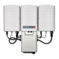
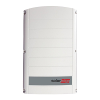
DC-DC converters for maximizing power harvesting via MPPT.

Three Phase Inverter Operation

Converts DC to AC power and receives monitoring data.

Chapter 2: Installing the Power Optimizers

Optimizer Installation Safety

Notes and warnings for installing Power Optimizers.

Installation Precautions and Compatibility

Module connection, mounting, connector compatibility, and safety features.

Step 1: Mounting and Grounding the Power Optimizers

Optimizer Mounting and Attachment

Determining location, marking holes, and attaching optimizers to the rack.

Grounding Methods on Metal Rails

Grounding optimizers on metal rails using star washer or plate.

Step 2: Connecting a PV module to a Power Optimizer

Module Connection Procedure

Connecting positive and negative terminals of module to optimizer.

Step 3: Connecting Power Optimizers in PV strings

PVRSS and String Connection Safety

PVRSS limits and connecting optimizers in series, minimizing EMI.

Step 4: Verifying Proper Power Optimizer Connection

Voltage and Polarity Verification

Measuring PV string voltage and verifying polarity.

Chapter 3: Installing the Synergy Manager and Synergy Units

Mounting and Connecting the Inverter

Instructions for vertical and horizontal inverter installation.

Chapter 4: Connecting PV Modules and AC to the Synergy Manager

Inverter Protection and Wiring Safety

Over-current protection and PE wire connection before AC wires.

DC Wiring and Polarity Verification

Connecting DC wires, ground wire, and ensuring correct polarity.

Chapter 5: Setting Up Communication with the Monitoring Platform

Verifying the Connection

Connection Verification Steps

Steps to check successful connection to monitoring platform.

Chapter 6: Activating, Commissioning, Configuring the System

On-grid Commissioning Procedure

Steps for activating installation for on-grid commissioning.

Verifying Activation and Commissioning

Verifying firmware, status, and LED indicators.

Pre-commissioning (Off-Grid) Steps

Items and steps for pre-commissioning without grid connection.

Reporting and Monitoring Installation Data

Appendix A: Errors and Troubleshooting

Identifying Errors

Methods for identifying errors using LEDs and monitoring platform.

Power Optimizer Troubleshooting Guide

Malfunctions and corrective actions for Power Optimizers.

PV String Voltage Troubleshooting

Troubleshooting high PV string voltage issues.

Communication Troubleshooting Procedures

Troubleshooting Ethernet (LAN) and RS485 communication issues.

Appendix B: Maintenance

Routine Maintenance and Visual Inspections

Performing yearly inspection and visual checks of the inverter.

Appendix C: Adding Optional Components

Appendix E: Interconnection Standards

Related product manuals