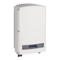
Do you have a question about the SolarEdge SE3K and is the answer not in the manual?
Explains symbols for notes, grounding, and cable connectors.
Explains caution and warning symbols for safety.
Details AC/DC switch operations and connector handling.
Use SolarEdge Designer to design the system.
Download the app to map string Power Optimizers.
Scan QR code using the Mapper app for installation.
Physical installation of the power optimizer onto the mounting system.
Connect the input cable from the PV module to the optimizer.
Connect the output cable from the optimizer to the PV string.
Verify array polarity and voltage per optimizer for correct connection.
Specifies indoor, outdoor, horizontal, and mounting clearances for optimal airflow and access.
Instructions for leveling, marking holes, and positioning template for mounting.
Details drilling holes and adding back support for stable installation.
Step-by-step guide for securely mounting the main units to the designated location.
Instructions for connecting interconnection cables according to labels between units.
Important warning to disconnect power before removing covers.
Steps for safely removing the unit covers to access internal components.
Guide for connecting PV strings to the Synergy Units, including unused connector handling.
Important note on fuse requirements for systems with more than 3 strings.
Cautions regarding lug types for aluminum and copper wires during connection.
Explains prohibition of functional earthing on DC side due to no transformer.
Supports 4-wire + PE or 3-wire + PE connections.
Procedure for connecting the PE wire first for safety.
Instructions for connecting L1, L2, L3, and N wires to the terminals.
Specifies lug types for aluminum and copper wires for AC connection.
Instructions for connecting the Ethernet cable for LAN communication to the unit.
Steps for connecting multiple inverters via RS485 communication.
Specifies CAT6 cable type and terminal connections for RS485.
Procedure for connecting the Wi-Fi communication module to the unit.
Procedure for connecting the cellular communication module to the unit.
Steps for installing the unit covers after internal connections are made.
Download and install the SolarEdge SetApp for configuration.
Turn on the DC switch as part of the pre-commissioning process.
Connect a power bank for pre-commissioning when AC power is unavailable.
Start and follow the SetApp for guided pre-commissioning steps.
Download and install the SolarEdge SetApp for configuration.
Turn on the DC and AC power for the commissioning process.
Start and follow the SetApp for guided commissioning steps.
Configure country, language, and pairing settings for the leader inverter.
Configure communication settings (RS485, Protocol) for the site.
Monitor inverter status, voltage, temperature, and production data.
Green LED indicates the system is producing power.
Blue LED indicates communication with the monitoring platform.
Red LED indicates a system error or fault.
| Output Power | 3000 W |
|---|---|
| Rated AC Power | 3000 W |
| Max. AC Power | 3000 W |
| Operating Temperature Range | -25 to +60 °C |
| Number of MPP Trackers | 1 |
| Cooling | Natural Convection |
| Warranty | 12 years |
| AC Frequency | 50/60 Hz |
| Max. Input Current | 11 A |
| Communication | RS485, Ethernet, Wi-Fi (optional) |




 Loading...