EasyManua.ls Logo

SolarEdge SE50K User Manual

SolarEdge SE50K
103 pages
To Next Page IconTo Next Page
Page #1 background imageLoading...
Page #1 background image
Installation Guide
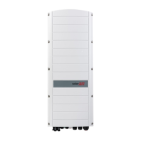
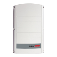
Three Phase Inverter with
Synergy Technology
For Europe and APAC
Version 1.2

Table of Contents

Questions and Answers:

SolarEdge SE50K Specifications

General IconGeneral
ModelSE50K
Maximum Input Voltage1000 V
Cooling MethodForced Air
Protection ClassIP65
Rated Output Power50 kW
Rated AC Power50 kW
Max DC Input Voltage1000 V
Dimensions780 x 541 x 316 mm
CoolingForced air
AC Voltage400 V
Communication InterfacesRS485, Ethernet
CommunicationRS485, Ethernet
Operating Temperature Range-25°C to 60°C

Summary

Support and Contact Information

HANDLING AND SAFETY INSTRUCTIONS

IMPORTANT INVERTER SAFETY INSTRUCTIONS

Chapter 2: Installing the Power Optimizers

Safety

Important safety notes and warnings applicable during power optimizer installation.

Step 1: Mounting the Power Optimizers

Procedure for determining mounting location and physically attaching power optimizers.

Step 2: Connecting a PV Module to a Power Optimiser

Instructions for connecting PV modules to power optimizers, including polarity.

Step 3: Connecting Power Optimisers in Strings

Guidance on connecting multiple power optimizers in series to form strings.

Step 4: Verifying Proper Power Optimiser Connection

Methods to verify correct connection and voltage output of power optimizers.

Chapter 3: Installing the Primary and Secondary Unit(s)

Mounting and Connecting the Primary and Secondary Unit(s)

Instructions for mounting the inverter units, including clearance and bracket alignment.

Chapter 4: Connecting the AC and Strings to the Connection Unit

Connecting the AC Grid to the Connection Unit

Procedure for connecting the AC power grid to the inverter's Connection Unit.

Connecting the AC Grid and Grounding to the Connection Unit

Detailed steps for connecting AC grid power and grounding to the Connection Unit.

Connecting the Strings to the Connection Unit

Procedure for connecting PV strings to the DC input terminals of the Connection Unit.

Selecting a Residual Current Device (RCD)

Chapter 5: Activating, Commissioning and Configuring the System Using the Inverter SetApp

Step 1: Activating the Installation

Procedure for activating the inverter and upgrading firmware via Wi-Fi connection.

Step 2: Commissioning and Configuring the Installation

Guide to using SetApp menus for inverter commissioning and configuration settings.

Step 3: Verifying Proper Activation and Commissioning

Steps to verify correct firmware, operational status, and optimizer pairing.

Reporting and Monitoring Installation Data

Chapter 6: Setting Up Communication

Creating an Ethernet (LAN) Connection

Step-by-step guide for establishing an Ethernet connection to the monitoring platform.

Creating an RS485 Bus Connection

Procedure for physically connecting inverters using an RS485 bus.

Verifying the Connection

Procedure to verify that the communication connection to the monitoring server is established.

Appendix A: Errors and Troubleshooting

Identifying Errors

Methods to identify error types using inverter LEDs, monitoring platform, or SetApp.

Appendix C: SafeDC™

Appendix D: External Fan Maintenance and Replacement

Appendix E: Replacing System Components

Replacing the Primary Unit

Detailed procedure for safely removing and replacing the Primary Unit.

Replacing a Secondary Unit

Instructions for safely removing and replacing a Secondary Unit.

Appendix F: Determining the Circuit Breaker Size

Determining the Size of an Inverter Circuit Breaker

Method to calculate and select the appropriate circuit breaker size for an inverter.

Three Phase Inverter with Synergy Technology - Technical Specifications (Europe and APAC)

Related product manuals