GENESIS
TM
DAS Operation Manual - Version 0.0 – Jan. 2019
©2019 SOLiD, Inc. All Rights Reserved. Confidential & Proprietary. Page 11
2.2.1 System Components and Network Topology
GENESIS
TM
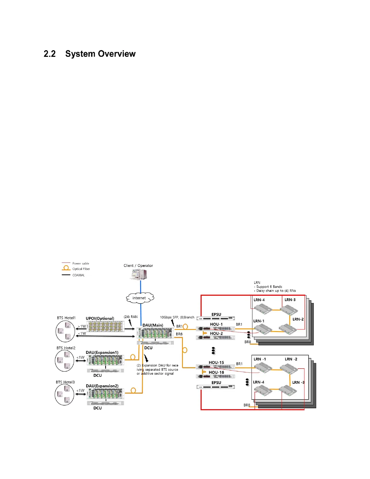
product series are that one common head-end delivers a more flexible network configuration.
Universal Point of Interface (UPOI): Attenuate high power signal from RAN and transport into DAU
Distribution & Aggregation Unit (DAU): Interface with analog RANs. Convert RF to digital and digital
into RF signals, and distributes digital signals to HOU via optical fiber
Decode Unit (DCU): Interface with DAU via UTP cable (CAT5). Decode signals input to DAU, and
Decode information is used for system ‘Auto Setup’
Hub Optic Unit (HOU): Interface with LRN via optical cable. Support the daisy chain of HOU to reduce
the number of optical fiber cables
Expansion Power Supply Unit (EPSU): Interface with HOU via D-SUB cable. Supply DC 57V to LRN.
Up to 24 LRNs can be powered via power cable (supported AWG 14 to 24)
Low Power Radio Node (LRN): Receive signal and power via optical cable and power cable (supported
AWG 14 to 24) from HOU
The following shows GENESIS
TM
network topology.
Figure 2.1 GENESIS
TM
Network Topology