6.6 Inverter Set
EPM has two versions: EPM-2G, EPM-5G. While inverter is working with EPM,
please be reminded to change the inverters settings as below:
6. Operation
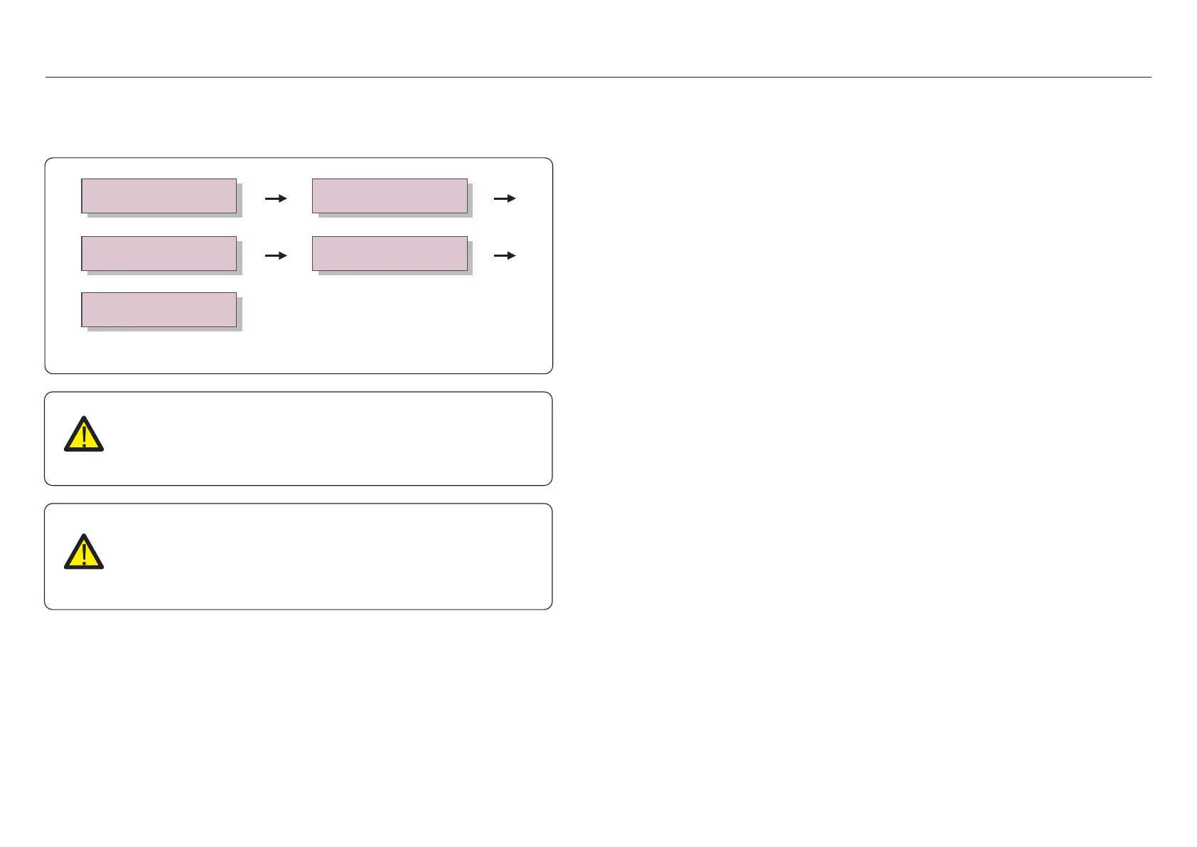
Advanced info.
Advanced Settings
->
YES=<ENT> NO=<ESC>
Password:0010
-> External EPM Set 5G EPM / Others EPM
->
ON/OFF
->
Figure 6.25
NOTE:
If you are using EPM-5G, please choose “5G EPM”, and set it “ON”, if you
are using EPM-2G. Please choose “Others EPM”, and set it “ON”, only
one setting needs to be set.
NOTE:
If “5G EPM” is chosen, for inverters produced before Nov 30th 2019
(SN: XXXXXX19B30XXXX)need to update the firmware, please contact with
Solis local service center or service@ginlong.com for instructions on
firmware update.
The EPM is designed in accordance with the most important international safety and
EMC requirements. Before delivering to the customer, the EPM has been subjected to
several tests to ensure its optimal operation and reliability.
In case of failure, the LCD screen will display alarm message.
The EPM can show Alarm it self or alarm from inverter. There are 3 alarm can be
showed on LCD:
1. Backflow
There are backflow current to grid, customer need to stop inverter. and check the
connections for the RS485 cable between EPM and inverter.
2. INV. fault
There are fault alarm in inverter, need to check inverter status.
3. Fail safe
RS485 AllFail: EPM has lost communication with ALL inverters
CT-Failsafe: Current Sensor failed
RS485Fail: EPM has lost communication with one or some of the inverters
7. Trouble Shooting
.29..28.
 Loading...