.9..8.
4. Installation4. Installation
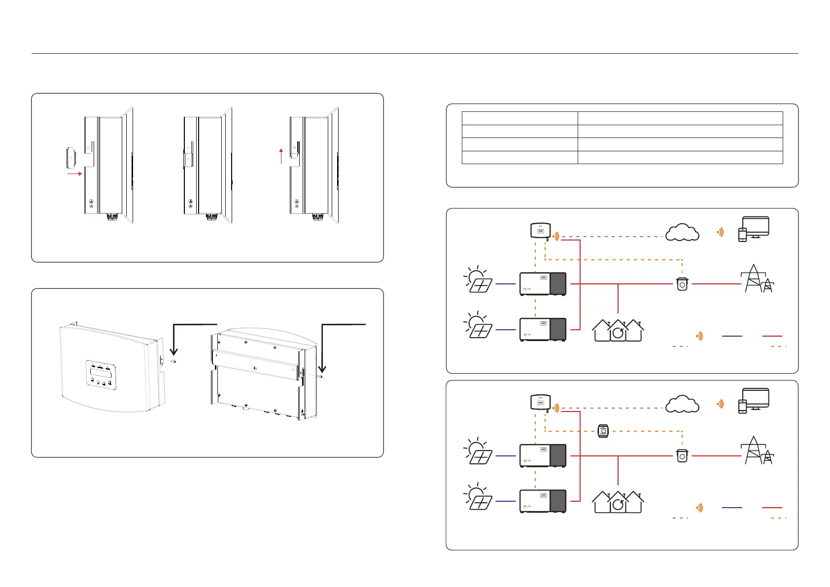
Hang the EPM in the bracket by the steps below .(see Figure 4.3)
Figure 4.3 Hang the EPM in the bracket
Fix the two screw at the side of bracket.(see Figure 4.4)
Figure 4.4 Fix the two screw
4.3 Electrical Connections
The EPM is designed for electrical connection without removing the cover.
The meaning of the symbols located at bottom of the EPM is listed in Table 4.1.
Figure 4.5 EPM1-5G, EPM3-5G system diagram
System connection diagram is as follows:
M4 locking screw
Grid
Meter
Comm_INV
AC voltage sampling terminal
Aconnect to Meter RS485 interface
Connect to solis inverters
Table 4.1 The meaning of the symbols located at bottom of the EPM
Communication Monitoring device or Upgrade Stick
M4 locking screw
Figure 4.6 EPM3-5G-PRO low voltage side system connection diagram
PV
PV
Solis Inverter
EPM
Data Stick
SolisCloud
PV Plant Digital
Management System
CT Grid
Loads
Internet
RS485 Communication Cable
Communication DC AC
PV
PV
Solis Inverter
EPM
Data Stick
SolisCloud
PV Plant Digital
Management System
CT Grid
Loads
Internet
RS485 Communication Cable
Communication DC AC
Smart Meter
(optional)