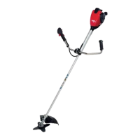
Connect Flex. Shaft, Throttle Cable and
Electrical Cables to Engine Flange
Turn lock lever (11) on engine flange to point
towards shaft. Hold lever in that position.
Insert Flex. Shaft (13) as far as possible and
allow lock lever to move back to lock position.
Open lid of the cable connection (12)
Connect electrical cables. Insert cable into cable
guides, connect throttle
cable and close lid.
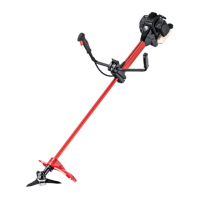
Installing loop handlebar
Fasten loop handlebar in front of the throttle handle.
Insert the first handlebar clamp (A) in the grip. Put
the handlebar at the arrow marking on the tube,
then place the second handlebar clamp below on
the tube, insert the nuts M5 (B) into the grip, screw
in the bolts M5x25 (C), and after straightening the
grip, tighten the bolts.
Fasten safety bar (4a) on loop handle with
2 screws.
Attention: For left-handed operators,
the safety bar has to be secured in
the opposite direction.
Assembly
For shipping purposes, the brushcutter is partly
disassembled and has to be reassembled prior to
use.
The brushcutter is only to be used after complete
reassembly.
A
B
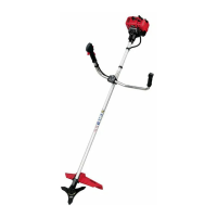
Connect Flex. Shaft with Coupling Sleeve
Remove red protection cap from both ends of
flex. shaft (13). Insert flex. shaft into coupling
connector (14) as far as possible and secure with
screw. The square of the flex. shaft has to be
connected to the receiver in the coupling sleeve.
1
2
3
Insert the shaft into coupling connector as far as
possible. Turn the tool while pushing so that the
geared inner shaft fits into the counter part. Insert
the screws and tighten.
4a
C
B
A
GB