EasyManua.ls Logo

Solo 132 User Manual

Solo 132
12 pages
Go to English
To Next Page IconTo Next Page
Page #1 background imageLoading...
Page #1 background image
1 STOP-Schalter
2 Gashebel
3 Gaszug
4 Rundumbügel
4a Sicherheitsanschlag
5 Choke-Hebel
6 Starthilfe "Primer"
7 Kraftstofftank
8 Startergriff
9 Luftfilterhaube
10 Zündkerze
11 Blockierhebel
12 Zugverbindung
13 Biegewelle
14 Kupplungsmuffe
15 Tragegestell
16 Rückenplatte
17 Tragegurt
18 Schutz
19 Schneidwerkzeug
Bedienungsanleitung Motorsense
Instruction manual Brushcutter
1 3 2
10
6
11
13
2
4
14
1
3
17
15
9
8
16
7
12
Typ/Model 1 3 2
19
18
4a
D 9 132 101
5
1. Multi-function Handle
2. Throttle Lever
3. Throttle Cable
4. Loop Handle
4a Safety Buffer
5. Choke Lever
6. Primer
7. Fuel Tank
8. Starter Handle
9. Airfilter Cover
10. Spark Plug
11. Lock Lever
12. Cable Connection Box
13. Flexible Shaft
14. Coupling Sleeve
15. Carrying Frame
16. Back Plate
17. Carrying Strap
18. Debris Shield
19. Metal Blade
Dieses Heft enthält die vom Typ 127/130 abweichenden Bedienungsmerkmale. Die Sicherheitshinweise und die restlichen
Anweisungen entnehmen Sie bitte der Bedienungsanleitung 127/130. This manual contains operating guide lines which differ
from those for the models 127/130. The saftety hints and instructions should be taken from the manual for 127/130.
Aufbau der Motorsense / Major components
Question and Answer IconNeed help?

Do you have a question about the Solo 132 and is the answer not in the manual?

Solo 132 Specifications

General IconGeneral
BrandSolo
Model132
CategoryBrush Cutter
LanguageEnglish

Summary

Assembly Instructions

Installing Loop Handlebar

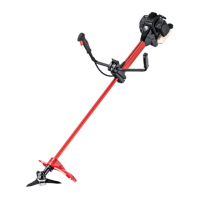
Fasten loop handlebar in front of the throttle handle using clamps, nuts, and bolts.

Connecting Shafts and Cables

Connect flex. shaft, throttle cable, and electrical cables to the engine flange.

Connecting Flexible Shaft

Insert and secure the flexible shaft into the coupling connector with a screw.

Installing Cutting Attachments

Installing Debris Shield

Attach the debris shield (18) to the shaft tube with clamps and bolts.

Installing Metal Blade

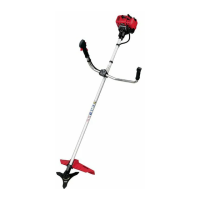
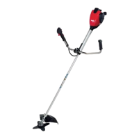
Mount metal blade (5) onto the splined drive shaft, securing with nut protector, washer, and lock nut.

Installing String Head

Screw the string head onto the arbor shaft against the pressure plate using left-hand thread.

Starting the Brushcutter

Start-up with Loop Handlebar

Procedure for starting the brushcutter with a loop handlebar, including choke and primer use.

Start-up with Warm Engine

Procedure for starting a warm engine or after a brief cut-off, leaving choke open.

Technical Data

Brushcutter Specifications

Details engine type, capacity, power, RPM, noise levels, acceleration, and weight.

Carburetor and Fuel System

Specifies carburetor type, fuel mixture, tank capacity, and air filter type.

Ignition and Gear Ratio

Details ignition system type and the gear head ratio for the brushcutter.

Related product manuals