Preparing the equipment for use
ENGLISH 9
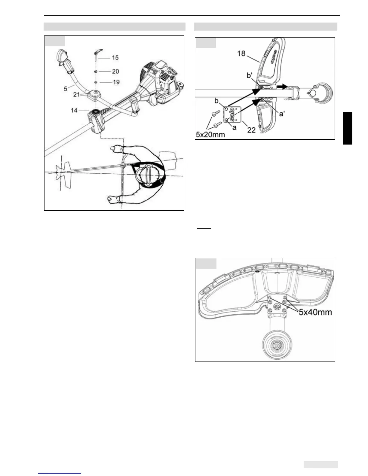
5.1 Installation - Bicycle handlebar
• Remove quick release screw (15) with sleeve (19)
and wavy washer (20) from the handle support
(14)
• Position the bicycle handlebar (5) with both pre-
assembled half shells onto the handle support
(14)
• Insert quick release screw (15) with sleeve (19)
and wavy washer (20) into the handle support, but
only so far that the quick release mechanism can
still flip over when the handle is sitting tight.
• The r.h. side of handle should be fitted as near as
possible to the handle support.
• For the optimum adjustment of the handle, flip
quick acting lock upwards and, if necessary,
release screws (21).
• Adjust the handle and flip quick acting lock (6)
back again.
• Now tighten screws (21).
Note: You will have achieved an optimum
adjustment, if the centre of the power tool is at the
centre of your body. Your elbow should be slightly
angled in operating position.
Important: Always lead the brushcutter with the
bicycle handlebar on the r.h. side of the body!
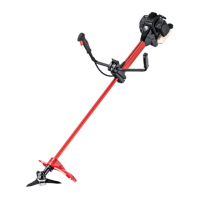
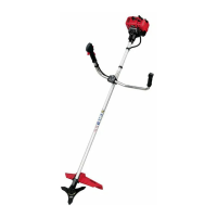
5.2 Shield installation
• Position the brushcutter with the output shaft
facing downward.
• Raise the shaft tube and slide the guard (18) along
the underside of the shaft tube into the correct
position (it should reach a stop at the angular
gearbox).
• Lay down the shaft tube with the guard.
• First insert a 5 x 20 mm bolt through hole a to
tighten the retainer (22) on the guard. Then insert
the second 5 x 20 mm bolt through hole b,
tightening finger tight only at this stage.
(Note:
The retainer has a raised part on the inside
near hole a. This allows the first bolt (which is
inserted through hole a) to be tightened straight onto
the block without any risk of the connection not being
straight.)
• Reposition the brushcutter with the output shaft
facing upward.
• Insert the two long 5 x 40 mm bolts through the
hole on the retaining bracket of the angular
gearbox and tighten the guard and the retainer.
The holes must line up exactly, so it may be
necessary to adjust the position of the guard first.
• To finish off, fully tighten the bolt in hole b.
Fig. 3
Fig. 2
Fig. 4