Do you have a question about the SOMFY Elixo 500 230V RTS and is the answer not in the manual?
| Power Supply | 230V |
|---|---|
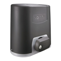
| Motor Type | Electromechanical |
| Maximum Gate Weight | 500 kg |
| Operating Temperature | -20°C to +60°C |
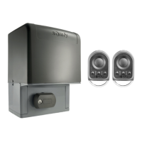
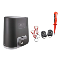
| Category | Gate Opener |
| Technology | RTS |
Specifications for product size and measurements.
Steps for installing the sliding gate opener onto the gate.
Details on physical mounting and lock mechanism states.
Guidance on correct measurements and installation verification.
Information on wiring, power supply, and fuse protection.
Initial introduction to DIP switch configurations for operation.
Detailed configurations for DIP Switch 3 settings.
Procedures for safety distance and programming remote controls.
Examples of different operating modes and their outcomes.
How to use the remote control for gate functions.
Comprehensive electrical wiring diagram for the system.
Settings for enabling or disabling the autotest function.
Wiring for safety photocells and mute cell outputs.
How DIP Switch 11 controls the indicator light.
Wiring for radio receivers and DIP Switch 6 for light activation.
Settings for the safety edge function using DIP Switch 6.
Guidance on connecting 230V accessories to the system.
Instructions for programming time-based functions and AUX inputs.
Procedures for programming remotes and checking compatibility.