Do you have a question about the SOMFY EXAVIA and is the answer not in the manual?
Product is a motorisation for hinged gates, compliant with EN 60335-2-103, ensuring safety of equipment and persons.
Checks required before motorisation: gate condition, stability, secure mounting, manual force, temperature suitability.
Power supply installation must comply with national standards and be done by qualified personnel for safety.
Safety instructions for underground and overground cables, requiring protective sheath and vehicle-resistant grommets.
General safety guidelines during installation, including removing jewellery and wearing protective gear.
Safe usage guidelines for users, including children, emphasizing supervision and keeping controls out of reach.
Monthly checks for wear, damage, and correct direction changes; use only original parts.
Safety warnings regarding batteries: keep out of reach of children, do not short-circuit, throw in fire, or recharge.
Identification of risk zones and measures to avoid or indicate dangers.
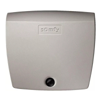
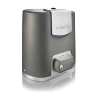
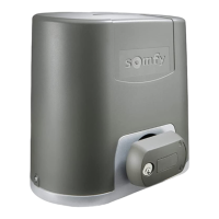
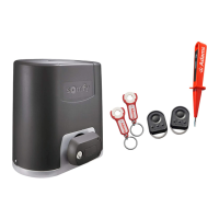
List of all components included in the EXAVIA kit, categorized into main parts and accessories pouch.
Diagrams illustrating the necessary dimensions and clearances for installing the EXAVIA motorisation system.
Describes the system's intended use for residential double door gates and its limitations.
Table detailing maximum gate leaf dimensions and weight based on wind strength and gate type.
Diagram showing the overall layout and placement of the EXAVIA motorisation components and optional accessories.
Description of the control unit's indicators (RADIO, P1, RESET, Indicator light) and their functions.
Verification steps for the gate, reinforcements, and pillars to ensure readiness for motorisation.
Requirements for power supply cables, connections, and cable routing for safe and compliant installation.
Specification of cable types, cross-sections, and quantities needed for motors, cells, and power supply.
List of tools not provided in the kit that are necessary for the installation process.
Information on required fasteners and fixings adapted to pillar/wall and gate leaf materials.
Step-by-step guide to measuring and marking key dimensions on the pillar for correct motor placement.
Procedure for marking the vertical AM and horizontal AH axes on the pillar for bracket alignment.
Instructions for drilling pilot holes in the pillars based on bracket markings and dimensions.
Steps for securely attaching the mounting bracket to the pillar, ensuring correct level and orientation.
Verification of the cylinder knob's position within the marking for correct motor assembly.
Instructions for adjusting the opening stop screw to set the desired gate opening limit.
Procedure for attaching the motor cylinder to the wall/pillar mounting bracket.
Steps for securely attaching the brackets to the gate leaves, ensuring correct alignment and function.
Guidelines for positioning and mounting the main control unit on a pillar or wall.
Instructions for fitting the sealing strip into the top of the control unit cover.
Ensuring the antenna is correctly positioned for optimal radio reception and performance.
Detailed steps for mounting the control unit bracket and the unit itself to the pillar/wall.
Wiring diagram and instructions for connecting the M1 and M2 motor cables to the control unit.
Procedure for safely connecting the 230V power supply cable to the control unit terminals.
Initial power-up procedure, checking indicator lights and status for auto-programming readiness.
Steps to set the desired opening position for the gate leaves using the cylinder's integrated stop.
Procedure for automatically configuring the gate's full opening and closing movements for proper operation.
Basic operation of the gate using the remote control for full opening and closing cycles.
Explanation of how the system detects obstacles and reacts during opening or closing movements.
Emphasis on training all users for safe operation, unlocking, and mandatory periodic checks.
Wiring and operation of photoelectric safety cells; system behavior when cells are blocked.
Wiring and operation of the flashing light, indicating gate movement and safety warnings.
Information on the backup battery, its purpose, technical data, and service life.
Instructions for wiring an optional offset antenna to extend radio range.
Wiring details for the optional video entry phone accessory.
Wiring and operational precautions for connecting the motor to a solar power supply.
How to use the pedestrian opening feature for partial gate opening via remote control.
Steps to program a remote control button for pedestrian opening functionality.
Procedure to disable the pedestrian opening functionality for a specific remote control button.
Description of the automatic closing feature and its interaction with photoelectric cells.
Steps to enable the automatic closing function using the remote control and control electronics.
Procedure to disable the automatic closing function of the gate motorisation.
Overview of Somfy RTS remote control types and their capabilities for gate automation.
Mapping of functions (opening, other RTS devices) to buttons on a 2-button remote.
Mapping of functions (opening, pedestrian, other RTS) to buttons on a 4-button remote.
Instructions on operating the gate (open, stop, close) with a 3-button remote control.
Step-by-step guide to programming new remote controls to the gate motorisation system.
Instructions on how to remove or clear programmed remote controls from the system.
Information on how to obtain support or help for motorisation faults and inquiries.
Procedure for safely opening the remote control and replacing the battery.
Steps to reset gate travel, parameters, or delete all programmed remote controls.
Procedure for manually unlocking/locking the motors to allow manual gate operation.
Table of common issues, indicator light flashes, and corresponding troubleshooting steps.
Detailed technical data including power supply, motor output, operating temperature, and IP rating.
| Brand | SOMFY |
|---|---|
| Model | EXAVIA |
| Category | Gate Opener |
| Language | English |
