Connection
GND
1. Connect the earth wire (factory-installed) to the earth clamp
(see diagram).
Mains connection
• Permissible cable cross-sections: 2.5 mm² max.
1 2 3
1. PE Protective earthing conductor
2. N Neutral wire
3. L Mains supply line AC 220 V - 240 V
Installation location
IMPORTANT INFORMATION!
As delivered the operator is installed on the left and the gate
opens to the left.
Operator left, calculating gate wing length
L = required gate wing length
A = available passage width
X = overlap (e.g.: gate wing - post)
245
X
A
L=245+A+ X
59
Terminal Cable colour Name
12 Green Motor
13 White Motor
18 White Gate OPEN sensor
19 White Gate CLOSED sensor
21 White Gate OPEN + CLOSED sensor ground
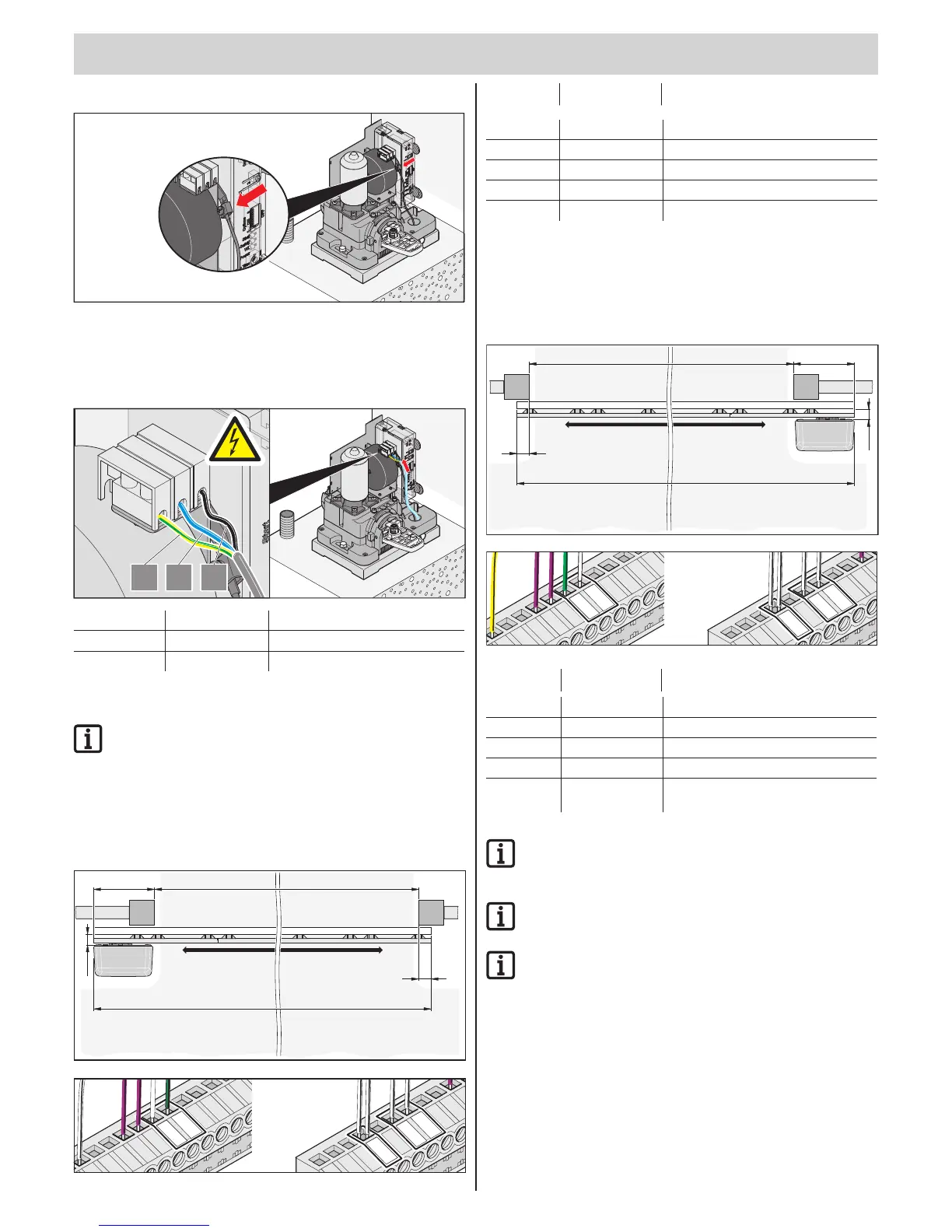
Operator right, calculation of gate length
L = required gate wing length
A = available passage width
X = overlap (e.g.: gate wing - post)
245
X
A
L=245+A+X
59
Terminal Cable colour Connection
12 White Motor
13 Green Motor
18 White Gate OPEN sensor
19 White Gate CLOSED sensor
21 White Gate OPEN + CLOSED sensor ground
IMPORTANT INFORMATION!
For right-hand installation reverse motor connection 12 + 13
and sensor lines 18 + 19.
IMPORTANT INFORMATION!
For terminal diagram overview, see overleaf.
IMPORTANT INFORMATION!
For max. line lengths see terminal plan overleaf.