Connection
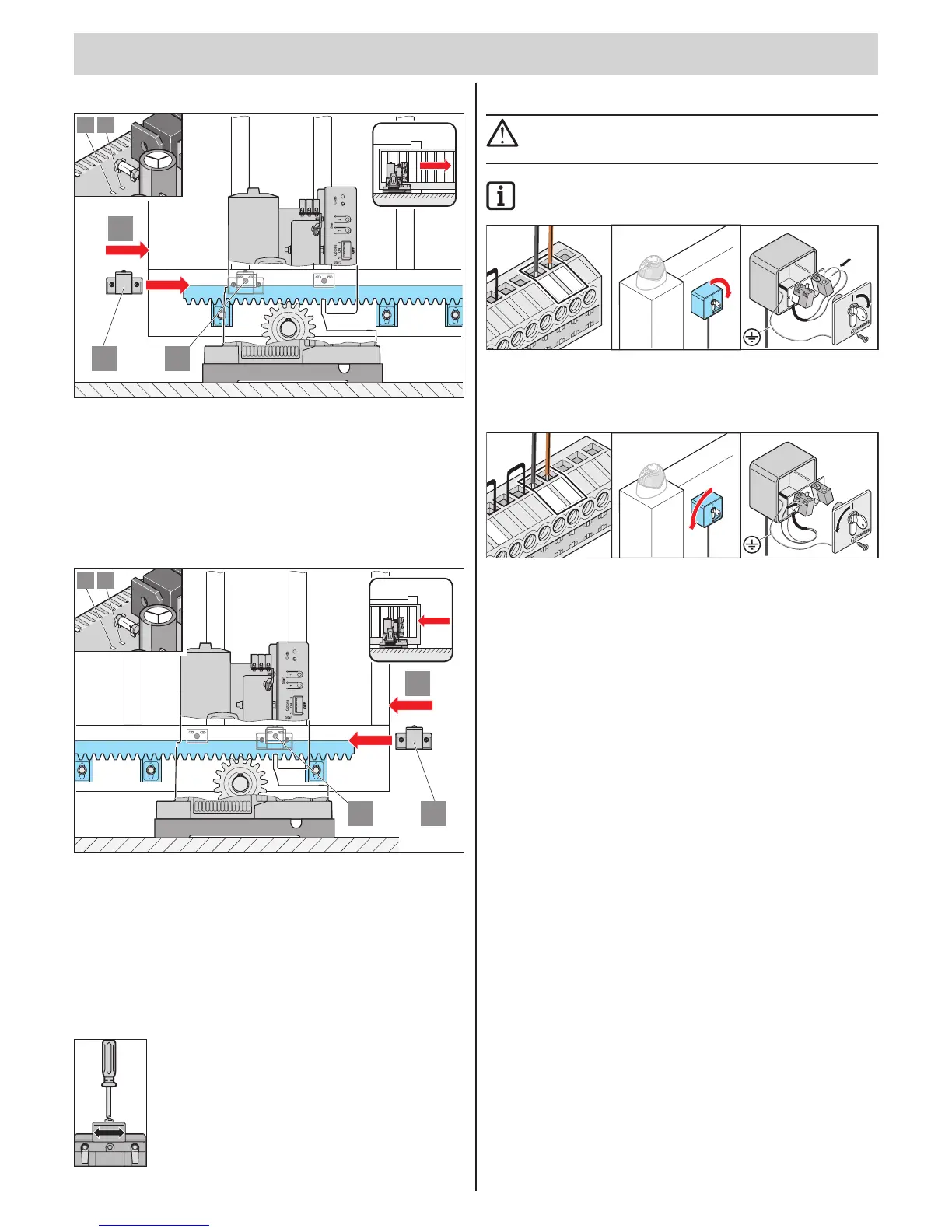
Set gate end position CLOSED
1
3
2
19 18
• Push the gate into gate end position CLOSED. (1)
• Slide the limit switch magnet (2) to sensor (3) until the latter switches
(LED on the control unit lights up).
Operator left: LED 18 -> gate CLOSED
Operator right: LED 19 -> gate CLOSED
• Tighten limit switch magnet 2.
Set gate end position OPEN
1
3
2
19 18
• Push the gate into gate end position CLOSED. (1)
• Slide the limit switch magnet (2) to sensor (3) until the latter switches
(LED on the control unit lights up).
Operator left: LED 19 -> gate OPEN
Operator right: LED 18 -> gate OPEN
• Tighten limit switch magnet 2
Note: Fine adjustment
Connecting buttons or key switches
ATTENTION!
When actuating the key switch the operator must keep clear of
the movement zone of gate and must have a direct view of it.
IMPORTANT INFORMATION!
The button inputs are potential-free!
7
6
5
4
3
2
1
S
O
MME
R
SO
M
MER
Button 2:
Terminals 4 + 5
What is button 2 for?
For settings see chapter "Functions and connections"
Denedopeningandclosing.(2-channelmode)
Button 1 opens and button 2 closes the gate.
Partial opening
Button 1 always opens and closes the gate completely.
Button 2 only opens the gate partially and closes the gate.
Dead man's function (switch on with TorMinal only)
Button 1 opens the gate while the button is pressed.
Button 2 closes the gate while the button is pressed.