Installation
14
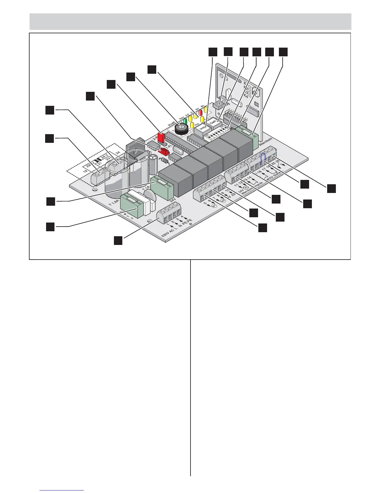
1. Button (imp.)
2. Connection of the external antenna
3. Button (walk-through)
4. DIP switches
5. Radio connector
6. Warning light fuse (11,12), slow-acting, 1A
7. Potential-free relay contact
8. Safety device connection
9. Button connection
10. Warning light connection
11. External consumer connection
12. Motor 2 (M2) connection
13. Motor 1 (M1) connection
14. Mains connection
15. Mains fuse, slow-acting, 1.6 A
16. Fuse 24 V DC (9, 10) slow-acting, 1 A
17. Primary transformer
18. Secondary transformer
19. TorMinal interface
20. Jumper, gate (1-leaf, 2-leaf)
21. Potentiometer (Gate 2) for force tolerance of Motor 2 (M2)
22. LEDs
16
15
22
1
2
3
4
5
6
12
13
11
9
7
14
10
8
17
21
18
19
20