Installation
15
Connecting operator to control
unit
CAUTION! DANGER OF ELECTROCUTION!
Before doing any work on the gate or operator, disconnect
it from the power supply and lock it to prevent reconnection.
The operator is only correctly detected by the control unit
after connection in a de-energised state.
CAUTION!
Never connect the operator directly to the AC 230 V
mains power.
Risk of deadly electric shock!
IMPORTANT INFORMATION!
Observe jumper setting for 1- and 2-leaf gate systems!
1-leaf gate
Terminal Description Description
5 M1 motor wire brown
6 M1 motor wire blue
7 M2 motor wire brown
8 M2 motor wire blue
1. Connect and set inactive leaf Motor 1 (M1).
(Inactive leaf: gate leaf which opens second and closes fi rst)
2. Connect and set active leaf motor 2 (M2) on control unit.
(Active leaf: gate leaf which opens fi rst and closes second)
3. Set all DIP switches to “OFF”.
4. Set jumpers: Set 1- or 2-leaf gate.
5. Connect control unit to the power supply.
“Mains” LED on.
“WL” LED fl ashes.
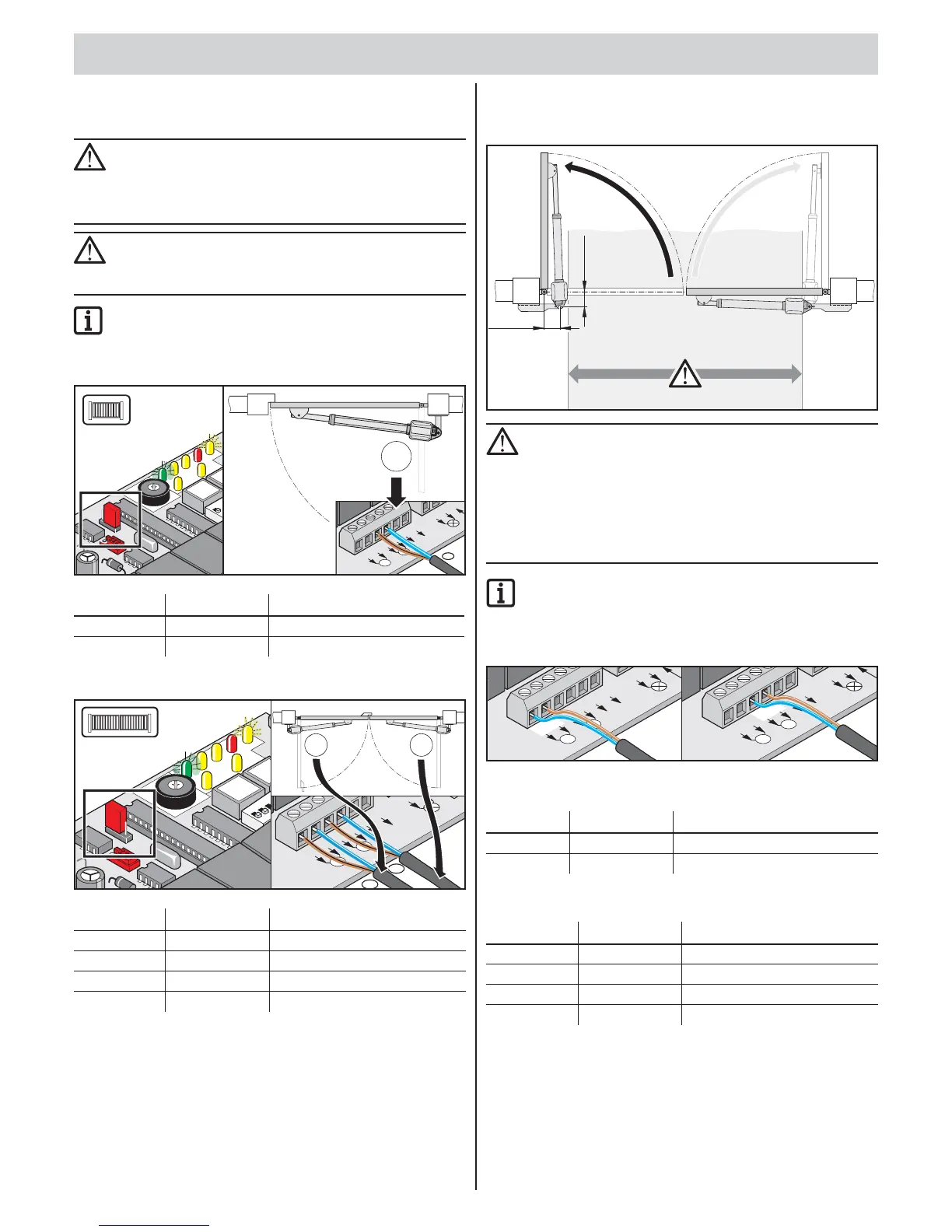
Installation situation: “Opening
gate outwards”
>120 mm
>120 mm
CAUTION!
Depending on the installation situation, the operators
protrude roughly 150 mm per side into the drive-through
and reduce the drive-through width.
• Swapping A/B dimensions:
A dimensions = B dimension in the A/B dimension table.
B dimensions = A dimension in the A/B dimension table.
• Set post and pillar fi ttings according to A/B dimensions.
IMPORTANT INFORMATION!
In the case of this “opening gate outwards” installation
situation, the connection deviates from the standard
connection.
Observe the following connection diagram!
M1
M
2
0V
24V
24V
War
nlicht
5
6
7
8
9
10
11
12
 Loading...