Installation
17
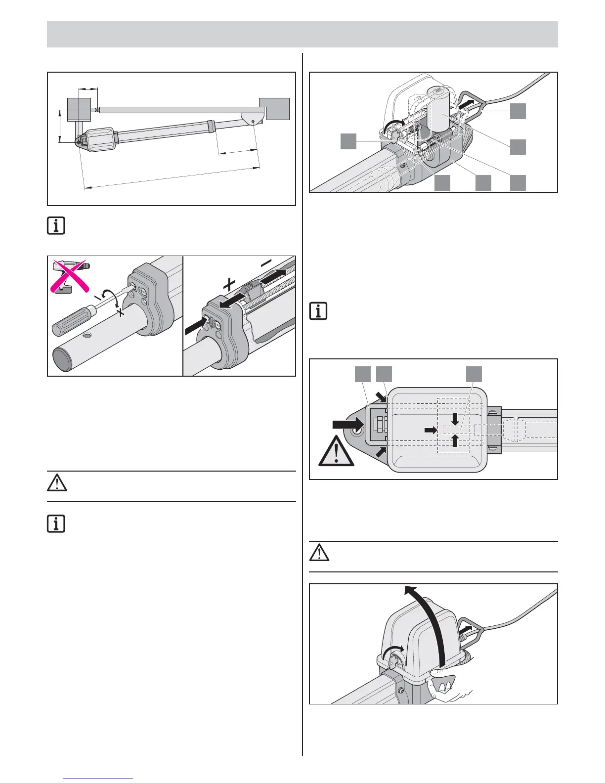
2. Setting “Gate CLOSE” end position
C = 1060 mm
C1 =
A
B
max
430 mm
max
IMPORTANT INFORMATION!
“Gate CLOSE” end position preset to C1
max
.
Do not exceed maximum values: C1
max
and C
max
.
close
open
clos
e
open
close
If necessary, readjust end position with a screwdriver.
• Extending travel length: Turn “close” setscrew in (+) direction.
• Reducing travel length: Turn “close” setscrew in (–) direction.
Locking and unlocking the
operator
CAUTION!
Before doing any work on the gate or operator, disconnect
it from the power supply and lock it to prevent reconnection.
IMPORTANT INFORMATION!
The emergency release lever can only be adjusted
with application of force and it engages noticeably.
In the event of a power failure, the gate can be moved by hand
after unlocking.
Unlocking operator
13 12
11
6
7
36
1. Turn key (6) 90° clockwise.
2. Pull emergency release bracket (11) from housing (12).
To simplify unlocking: Move gate leaf manually.
Operator is unlocked
The gate can now be moved by hand.
Lock operator
1. Move the emergency release bracket (11) towards housing (12).
IMPORTANT INFORMATION!
The emergency release bracket (11) must be almost
in contact with the housing (12).
If the operator is not completely locked, it will damage
the motor (7).
11 12 13
2. Turn key (6) 90° anti-clockwise.
The gate can now only be moved using the operator.
Removing cover
CAUTION!
Before doing any work on the gate or operator, disconnect
it from the power supply and lock it to prevent reconnection.