Functions and connections
23
Safety instructions
Observe cable requirements:
Property Value Terminals
Cross-section 0.25...2.5 mm
2
All terminals
Maximum length 10 m 5 to 10
35 + 36
Maximum length 30 m 21 to 34
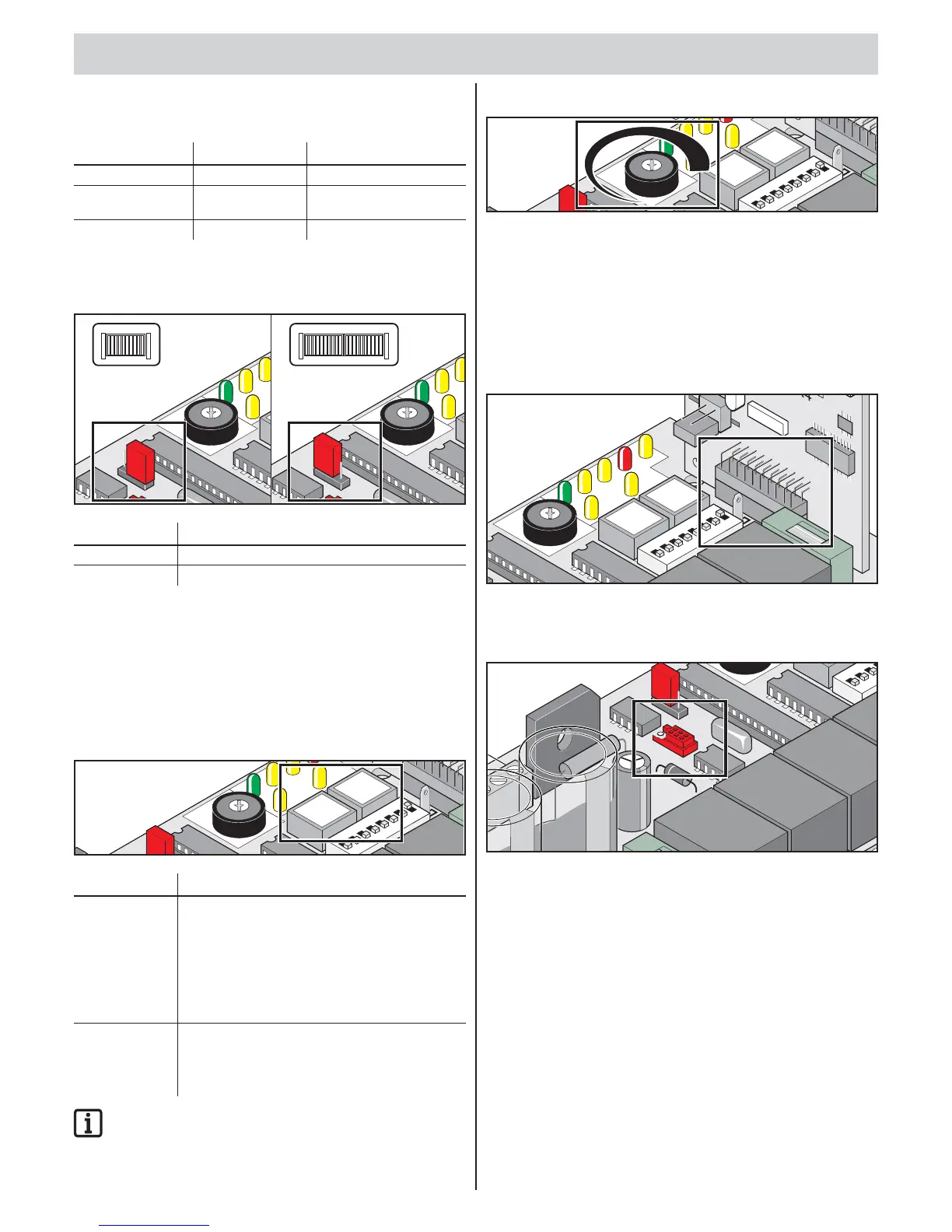
Jumper
Select 1- or 2-leaf gate.
L
E
D1
LED
6
L
E
D
4
LE
2-Fl.
1-Fl.
Kr
aft
3
0
9
Im
N
etz
Au
f
Zu S
H
6
P
1
L
E
D
1
L
E
D
6
L
E
D4
L
2-Fl
.
1
-
F
l.
Kraft
3
0
9
Im
Netz
Au
fZ
u
S
6
P
1
Label Description
2-leaf/1-leaf 1-leaf: Jumper on bottom pins or removed
2-leaf: Jumper on top pins
Setting 1- or 2-leaf gate (jumper)
1. Reset the control unit.
2. Replug jumpers.
3. Reset the control unit.
4. Perform learning run.
Button on control unit
L
ED 1
L
ED
2
L
E
D
6
L
E
D
4
L
ED 5
L
E
D
Label Description
Pulse Pulse button
• opens both gate leaves.
• Stops moving gate leaf with walk-through gate.
• Gate leaf with walk-through gate open:
Opens gate leaf with stop.
• Function sequence: Open – Stop – Close –
Stop – Open…
Walk-through Walk-through gate button
• Opens gate leaf with walk-though gate.
• Function sequence: Open – Stop – Close –
Stop – Open…
IMPORTANT INFORMATION!
Button (walk-through) operates only if the gate leaf with stop
is fully closed.
Potentiometer for force tolerance
L
E
D
1
L
E
D
2
L
ED 6
L
E
D
4
LED
5
L
ED
3
The force tolerance to the automatically learned force is set with
the “P1” potentiometer.
The “P1” potentiometer setting is imported again at every start.
• Minimum force tolerance = left stop (0)
• Maximum force tolerance = right stop (9)
Radio connector
Slot for radio receiver. Installed on delivery.
L
ED 1
L
E
D
2
L
E
D
6
L
E
D
4
LED 5
LE
D
3
L
ED 7
Kraft
3
0
9
I
mp.
Geh.
Netz
Auf Z
uS
H
W
L
F
U
N
K
T1
A
Wa
r
n
O
FF
6
P1
Ge
h
.
Imp.
2
1
ON
DI
P
3
4
5
6
8
7
FUSE
5x20
TorMinal interface
See TorMinal installation and operating manual.
2
-F
l.
1
-F
l.
0
O
FF
24
2
1
ON
3
FUSE
Functions and connections
 Loading...