Functions and connections
26
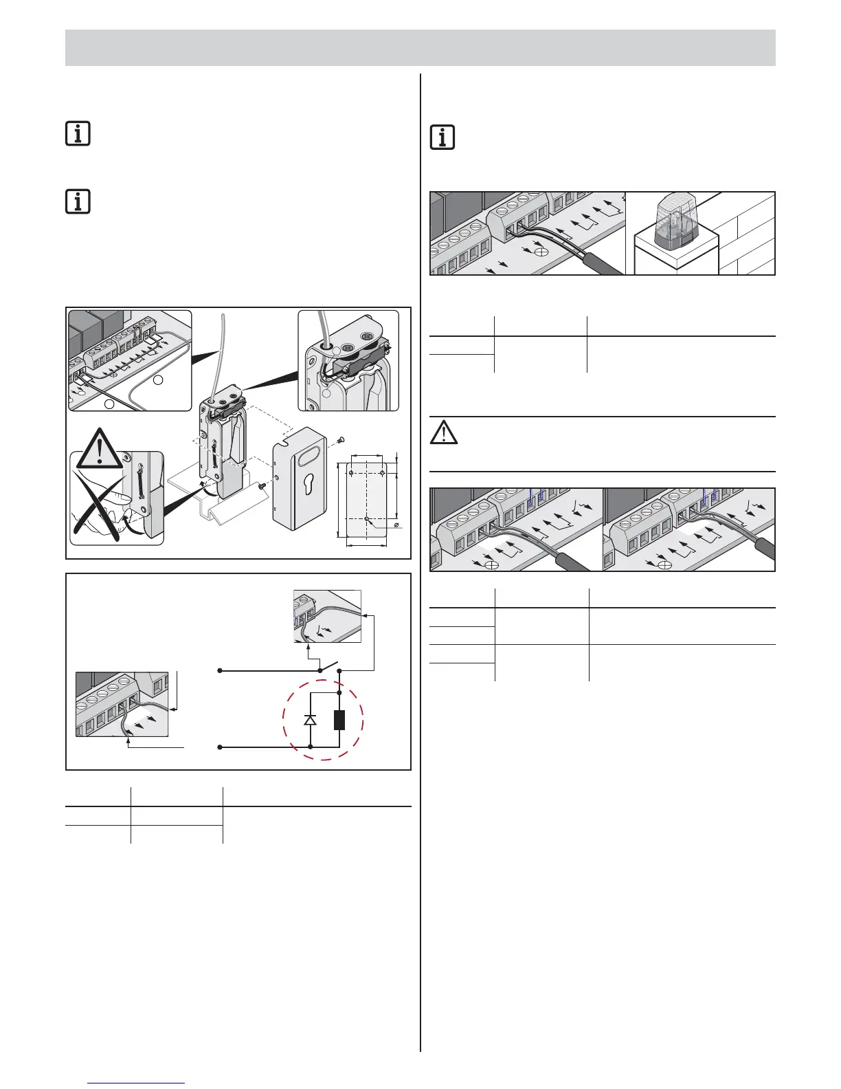
Connecting electric lock
Available as an accessory.
IMPORTANT INFORMATION!
The electric lock is operated with direct-current, unregulated
transformer voltage. The transformer voltage can fl uctuate
between DC 22 V …DC 32 V when fully loaded.
IMPORTANT INFORMATION!
The connection diagram is for a DC 24 V electric lock. DC 12 V
electric locks must not be connected without consultation
with the manufacturer.
Use only electric locks approved by SOMMER Antriebs- und
Funktechnik GmbH. Check for the correct polarity.
If other types of electric locks are used, the guarantee
for the motor control unit will be cancelled.
52
76,5 17
124
67
3x 6
B
Warnl
M
1
M
2
0
V
2
4V
2
4
V
Wa
r
n
lic
h
t
I
m
p
u
ls
G
e
htür Sic
h
er
h
.S
o
n
d
er
fkt.
7
8
91
0
1
1
1
2
1
3
1
4
15
16
1
7
1
8
25 26
F
F
2
5
2
6
10
9
+
-
-
+
#3205
D
L
+
–
(0 V)
(24 V)
10
9
26
25
0V
24
Terminal Description Description
9 0 V DC 24 V electric lock connection,
limited to 2 A at max. 48 W power.
10 24 V
Connecting warning light
Available as an accessory.
IMPORTANT INFORMATION!
The warning light is operated with direct-current, unregulated
transformer voltage. The transformer voltage can fl uctuate
between DC 22 V …DC 32 V when fully loaded.
24V
24V
Wa
r
nlicht
Impuls
Gehtür
Si
c
Setting the function, see DIP switches 4 + 5.
Terminal Description Description
11 24 V warning light Connection for DC 24 V warning light
with 1 A fuse for max. 24 W power.
12
Connecting button
CAUTION!
Only use the connection for potential-free closer contacts.
External voltage can trigger severe power surges and damage
or destroy the control unit.
1
5
16
Terminal Description Function
13 Pulse Connection for pulse transmitter
for actuating one or both leaves.
14
15 Walk-through
gate
Connection for pulse transmitter
for actuating a gate leaf.
16
• 1-leaf gate: Start 1 and Start 2 buttons have the same function.
• 2-leaf gate: Button 2 contact is needed for the walk-through
gate function.
1-contact button
• 1-leaf gate buttons at terminals 13 + 14 or 15 + 16
• 2-leaf gate buttons at terminals 13 + 14
2-contact button
• Walk-through terminal 15 + 16
• Both gate leaves 13 + 14
 Loading...