Functions and connections
28
Connecting external consumers
IMPORTANT INFORMATION!
The external consumer is operated with direct-current,
unregulated transformer voltage. The transformer voltage
can fl uctuate between DC 22 V …DC 32 V when fully loaded.
24V
5
x
20
9
1
0
Terminal Description Description
9 0 V DC 24 V output with 1 A fuse max.
20 W power.
10 24 V
Connecting potential-free relay
contact
CAUTION!
Operate under resistance load only. Use only electric locks
approved by SOMMER Antriebs- und Funktechnik GmbH.
Check for the correct polarity.
If other types of electric locks are used, the guarantee for the
motor control unit will be cancelled.
5
1
6
17
1
8
25 26
Relaiskont.
Terminal Description Description
25 Relaiskont. Connection for e.g. electric lock max.
8 A, DC 24 V under resistance load.
26
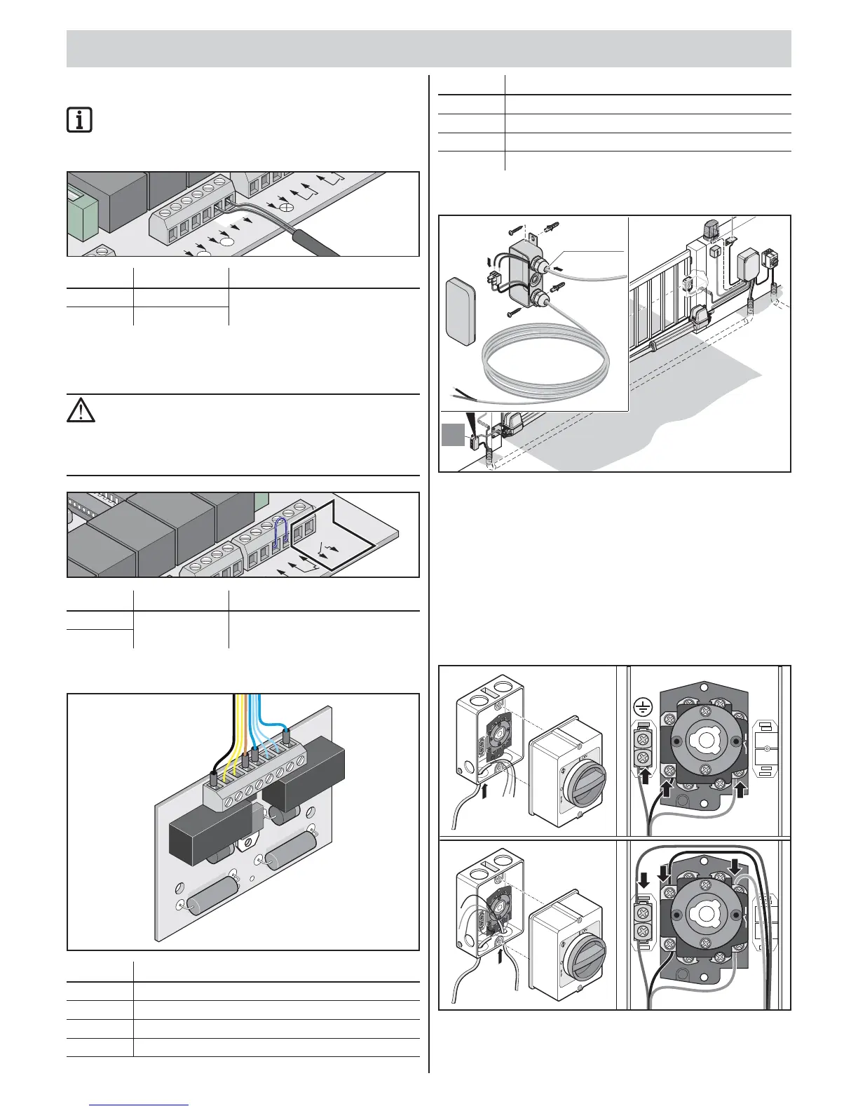
Connecting motor
87654321
Terminal Description/cable colour
1 24 V feed line from control unit, blue
2 Limit switch gate “CLOSE”, blue
3 Limit switch gate “CLOSE”, blue
4 Motor, blue
Terminal Description/cable colour
5 24 V feed line from control unit, brown
6 Limit switch gate “OPEN”, yellow
7 Limit switch gate “OPEN”, yellow
8 Motor, black
Attaching connecting cable set
1
4
7
P
2
5
8
0
M
3
6
9
E
s
c
O
S
O
M
M
E
R
TO
R
A
N
T
R
I
E
B
E
4
4
1,5 mm –2,5 mm
2
2
1. Fasten terminal box with screws through the eyelets.
2. Connect cable with the same number:
▫ blue with blue
▫ brown with brown
▫ etc.
3. Tighten PG fasteners well to prevent ingress of moisture into
the terminal box.
4. Close terminal box.
Main switch
L1
L
1
L2
L
2
L3
L
3
T
3
T
3
T
2
T
2
T
1
T
1
N
N
N
N
O
O
L1
L1
L2
L2
L3
L3
T3
T3
T2
T2
T1
T1
N
N
N
N