Installation
9
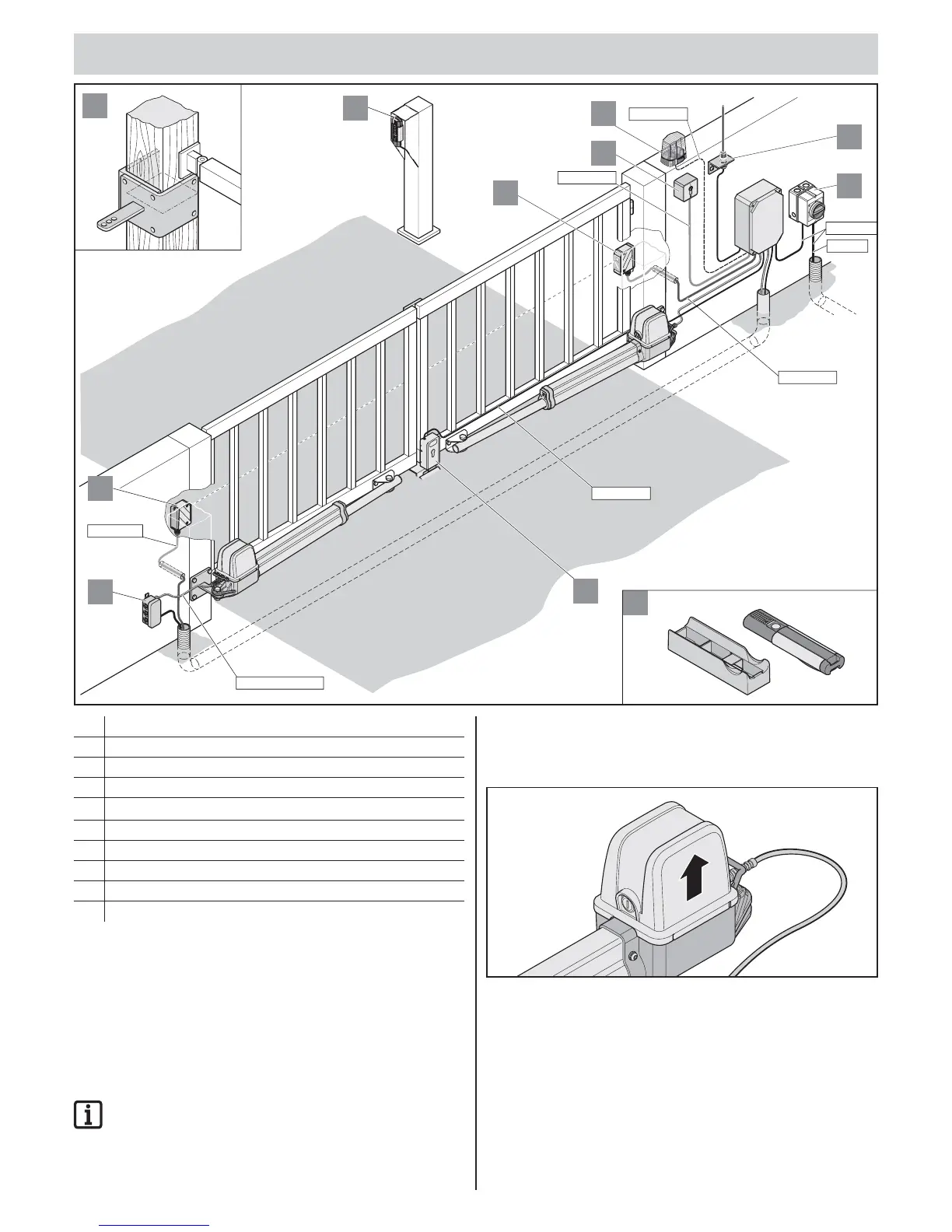
1. Warning light DC 24 V/24 W
2. Key switch (1 or 2 contact)
3. Photo eye
4. Connecting cable set, 7 m
5. External antenna (including cable)
6. Main switch (lockable)
7. Electric lock DC 24 V
8. Telecody
9. Car/wall holder for transmitter
10. timber post fi ttings
Tips for installation
Defi ne the installation location of the control unit together with the operator.
Install the housing so that it is hidden from unauthorised persons to prevent
deliberate damage to the housing and control unit.
Attach threshold or stop bar to the gate:
• Gate leaf length longer than 2 m
• 2-leaf gate
IMPORTANT INFORMATION!
Additional pulse transmitters are: transmitters, Telecody,
wireless indoor switches and key switches.
For transmitters, Telecody or the radio interior push-buttons,
no connecting line must be installed for operation.
Operator installation position
Install operator horizontally. Note installation position of motor; it must
always point upright.
Installation
9
5
4 x 0,75 mm
2
3 x 1,5 mm
2
O
S
OM
M
E
R
T
O
RAN
T
R
I
E
B
E
1
2
2 x 0,75 mm
4 x 0,75 mm
2
2
6
2 x 0,75 mm
2
3
2 x 0,75 mm
2
4
7
3
AC 230 V
P
E
M
C
S
8
10
2 x 1,5 mm –2,5 mm
2
2