TDR-420 – USER MANUAL 5
• It is unacceptable to operate the device when:
a damaged meter which is completely or partially out of order,
a meter with damaged insulation,
a meter stored for an excessive period of time in disadvantageous conditions (e.g. excessive
humidity). If the meter has been transferred from a cool to a warm environment with a high level
of relative humidity, do not start measurements until the meter is warmed up to the ambient tem-
perature (approximately 30 minutes). Battery spill and damage to the meter may occur if dis-
charged batteries are left in the meter.
• Do not operate a meter with an open or incorrectly closed battery (accumulator) compartment or
power it from other sources than those specified in the present manual.
• Repairs may be performed only by an authorised service point.
CAUTION!
•
Only standard and additional accessories for a given device should be used, as
listed in section 15 Accessories. Using other accessories may cause damage to
measuring terminals and introduce additional measurement uncertainty.
•
Do not connect the device to cables under voltage. Under such conditions, the
measurement will be invalid, and the device may be damaged!
3 Principle of operation
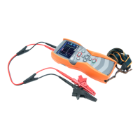
TDR-420 measures time of signal run (probe pulse) through a cable pair from the connection
point (end of the dead zone) to the end of the cable or to the nearest damage. The reflectometer
may also determine the length of the section, where the cable insulation is wet, so the required
maintenance action may be taken.
The pulses transmitted by the device, run along the cable at the Velocity of Propagation (VoP),
which depends on the electrical parameters of the cable, particularly on the material of cable insula-
tion. Based on user-selected VoP value and the measured pulse time, the reflectometer:
• calculates the distance to the disturbance of wave impedance of the path and
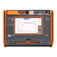
• displays the image of the cable in the form of a reflectogram, which shows all discontinuities of
wave impedance in the tested section.
The horizontal axis is used to determine the length of the tested cable section as well as the dis-
tance to the damage and anomalies in the tested cable. The vertical axis is used to determine
changes in the impedance of the tested test cable.


 To Next Page