0789P300-E Installation Superstatic 789 EN 29-05-2017 2 Sontex SA, 2605 Sonceboz, Switzerland
Mounting of the integrator for a cooling application
Only the flow meter can be fully isolated. Separate the integrator from the flow meter and fix using the wall support aid
It is recommended to separate the integrator from the flow meter and installed at a sufficient distance from the flow meter if:
- The meter has to be installed in a confined space
- The meter is in connection with mounting in condensing environments
- To prolong the battery life time
The pipes are generally free from air before the installation is brought into service. Follow the insulation instructions for cooling installations. Final commis-
sioning must be performed and documented.
After mounting and before commissioning purge system > 10 min at qp to avoid air bubbles.
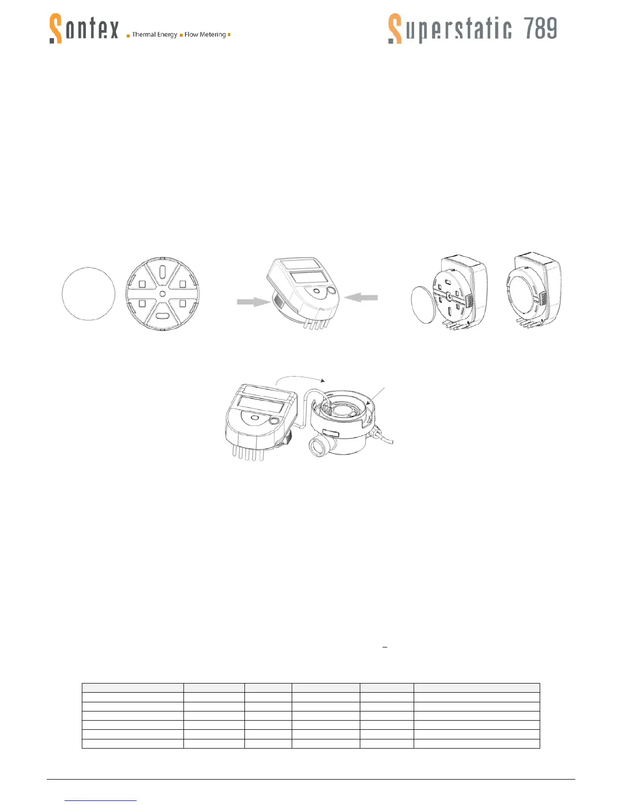
Wall-mounting of the integrator
The integrator can be separated from the flow meter and fixed against a wall using the wall fixture supplied with the energy meter. If possible, install the
wall fixing component above the flow meter.
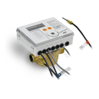
The wall fixing component, together with a double-sided adhesive tab, is delivered with the Superstatic 789 (Figure 1).
The wall fixing component can also be screwed on to the wall (screws are not supplied).
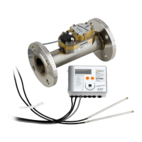
To separate the integrator from the flow meter press laterally with one hand on the two locking buttons, while pulling the integrator upwards (Figure 2).
Fix the integrator onto the wall fixing component taking care not to jam the cable which connects the integrator to the flow meter and stick the adhesive tab
behind the wall component. Secure the assembly to the wall (Figure 3).
Figure 1
Figure 2
Figure 3
To remove the integrator from the wall support, it will be sufficient to press laterally on the two locking buttons while pulling the assembly towards you.
Rewind the connection cable at the position provided for this purpose on the flow meter (1) and re-insert the integrator (2).
Mounting of the temperature sensors
The temperature sensor in the flow meter has a colourless marking.
The temperature sensor with the orange mark indicates that the sensor must be mounted in the pipe “opposite” to the Superstatic 789.
Example: If the flow meter is installed on the warm side (Hot Pipe), the temperature sensor with the orange mark will be mounted in the cold side (Cold
Pipe).
The Superstatic 789 is delivered with temperature sensors having a cable length of 1.5 m.
The temperature sensors form a sub-assembly with the integrator. The temperature sensor cables must be neither shortened nor lengthened.
The temperatures of use displayed on the label must be respected.
A temperature sensor may be fitted directly in the Superstatic 789 flow meter. The temperature sensors will preferably be fitted directly, in other words one
temperature sensor will be fitted in the flow meter while the other sensor will be installed on the other side of the heat exchanging circuit.
Tighten the nuts of the sensors Ø 5 and Ø 5.2mm with ½ to ¾ turn from the compression of the seal.
When sensor pockets are employed, these must be used specifically for the two temperature sensors and must correspond to the list set out below.
Asymmetrical mounting is also possible. In that case the temperature sensor having a cable marked with orange will be fitted in the other side of the heat
exchanging circuit in a sensor pocket defined according to the table set out below.
To guarantee accuracy in this type of use, the following condition must be respected: at a flow rate < 100 l/h, the temperature difference has to be equal or
larger then 6K, ∆T
min
≥ 6 K.
Make sure that the sensors are mounted until they stall with the bottom of the sensor pocket.
Sensor pockets list
 Loading...