0789P300-E Installation Superstatic 789 EN 29-05-2017 3 Sontex SA, 2605 Sonceboz, Switzerland
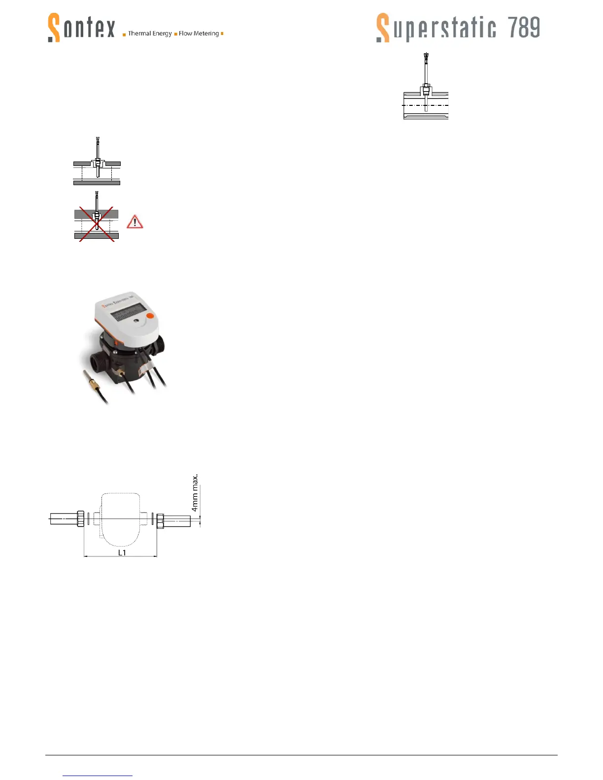
Direct mounting in a T tube
The temperature sensor is on the same level and perpendicular to the pipe axis (DN15, DN20):
Fitting temperature sensors for cooling applications
Insulation shall only be mounted as far as the fixing screw.
The temperature sensor fixing screw must not be covered by any kind of insulation. This likewise applies if the sensor is
fixed directly in the flow meter.
Installation of the Superstatic 789
To install the Superstatic 789, the following steps must be respected :
Flush out the installation pipes carefully in compliance with the DIN/EN standard
specification.
Close the shutoff valves before and behind the meter.
Open the drainage valve to reduce the pressure and discharge the water contained in
the pipe between the two shutoff valves.
Consider the direction of flow circulation. Check the flow direction with the arrow figur-
ing on the flow meter.
Place a gasket on each side of the flow meter. Only use appropriate new gaskets.
Make sure that the gaskets are carefully positioned in relation to the water pipe and
flow meter unions.
Tighten the fixing nuts firmly by hand. Then tighten up using a mounting tool as de-
scribed below.
Install the temperature sensor.
Turn the display into the desired position for reading.
Check the waterproof of the meter placed under pressure.
Seal the flow meter and the temperature sensors.
Precautions to be observed during the mounting :
Between the axis of the pipes an offset (misalignment) of 4mm maximum is tolerated
Use only the EPDM gaskets supplied with the Superstatic 789.
Tightening of the two fixing nuts will be done with a torque wrench with a maximum
tightening torque of:
25 Nm for flow meter qp1,5 m
3
/h G ¾" (DN15).
50 Nm for flow meters qp1,5 m
3
/h G 1" (DN20) and qp2,5 m
3
/h G 1" (DN20).
Mounting distance L1 for the flow meter:
L = 110 mm, qp1,5 m
3
/h G ¾" (DN15) : L1 = 113 ± 1mm
L = 130 mm, qp1,5 m
3
/h and qp2,5 m
3
/h G 1" (DN20) : L1 = 133 ± 1mm
Mounting cable for the pulse input function
The pulse inputs are built with SELV circuits (Safety Extra Low Voltage) and must be only connected with SELV circuits. The electrical characteristics are
displayed on page 8.
Mounting cable for the pulse output function
The pulse outputs are built with SELV circuits (Safety Extra Low Voltage) and must be only connected with SELV circuits. The electrical characteristics are
displayed on page 8.
 Loading...