0739P310 IG_Installation Guide Supercal 739_V01_2006_en_de_fr_it 3 Sontex SA, 2605 Sonceboz, Schweiz, Suisse
Installation guide Supercal 739
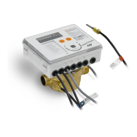
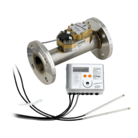
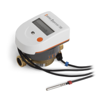
The compact mechanical single or multiple jet thermal energy meter Supercal
739 is a precision measuring instrument approved for individual metering of
heating systems. It must be handled with care.
The Supercal 739 is available in a heating or cooling version and determines the
thermal or cold energy exchanged by a heat-bearing fluid in a heat exchanger
circuit.
The Supercal 739 complies with the requirements of the European Directive
MID 2014/32/EU modules B and D and of the standard EN 1434 class 3.
Important
The energy meter may only be used under the conditions indicated on the manu-
facturer’s rating plate! The seals must not be removed or may be removed only
by authorised persons.
If these conditions are disregarded, the warranty and the calibration will no longer
be the manufacturer’s responsibility.
Do not shorten the cable between the flow meter and the integrator and the
cables for the temperature sensors or modify them in any way whatsoever.
Before installation
Check the installation data and compare them with the specific characteristics of
the thermal energy meter.
Installation
The related prescriptions in the standard EN1434-6 must be respected when
installing the Supercal 739.
Depending on version and use (heat and/or cooling meter), the energy
meter must be fitted on the “cold” or “hot” pipe side of the installation in
compliance with the indications showed on the LCD display, service menu
and/or config menu (if available).
Place the flow meter according to the direction of the fluid (an arrow is visible
on the flow meter).
The energy meter must be fitted between two shutoff valves and ahead of any
monitoring valve to avoid any interfering influence.
Mixed mounting positions (horizontal and vertical) should be avoided in any
installation!
Final commissioning is recommended and documented.
For all further information such as for example settings for radio transmis-
sion, please refer to the detailed User manual of the Supercal 739 heat
meter available at:
The QR code located on the label of the carton or
on the integrator allows to access to the Installation
Manual on a smartphone.
Wall-mounting of the integrator
The integrator can be separated from the flow meter and fixed against a wall
using the wall fixture supplied with the energy meter, possibly above the flow
meter.
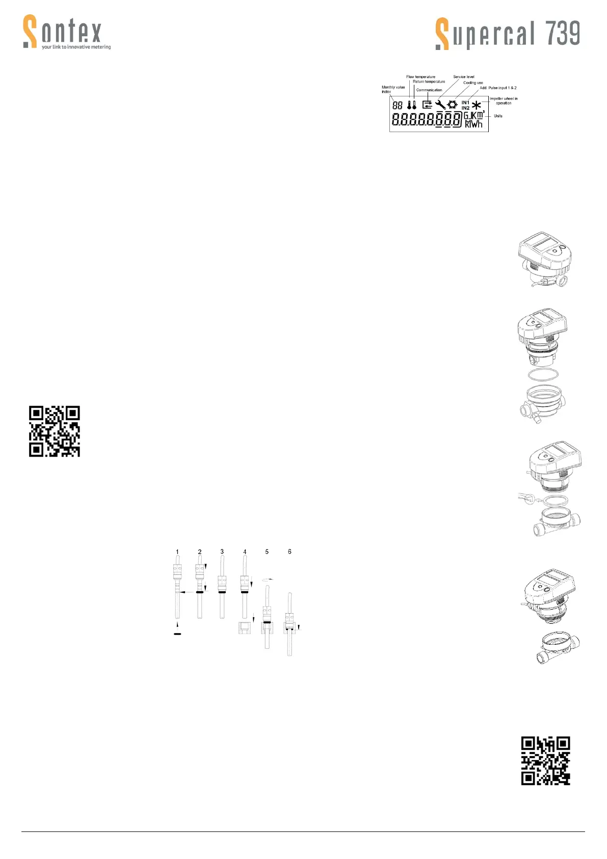
Mounting the temperature sensors
The temperature sensor with a colourless marking is fitted close to the flow meter
or directly into it. The temperature sensor cable marked with an orange label is
mounted in the “opposite” pipe (in the other side of the heat exchanging circuit) of
the one with the Supercal 739.
Check whether the O-ring is in the
3rd groove (arrow)
1. If not, push the O-ring into the
corresponding groove
2. Push the screw connection up to
the O-ring
3. Insert the temperature sensor into
the tube fitting
4. As soon as the O-ring is in contact
with the thread, screw in the
temperature sensor by hand
up to the stop
5. Then tighten with a maximum tightening torque of 1.4 Nm (corresponds to
approx. one ½ turn)
Asymmetrical mounting is also possible. In that case the temperature sensor
having a cable marked with orange will be fitted in the other side of the heat
exchanging circuit in a sensor pocket.
For applications with non-symmetrical integrated temperature sensor pair re-
stricted rated operating conditions are to be in accordance with the lower limit of
the flow value and the lower limit of the temperature difference:
qi ≥ 200 l/h at ∆T
min
= 3K or qi ≥ 60 l/h at ∆T
min
≥ 6 K.
Make sure that the sensor is mounted until they stall with the bottom of the sen-
sor pocket.
Error codes
Err 1: Flow higher than 1.2 x qs or defective hydraulic sensor.
Err 2: Measured temperature outside the homologated range or temperature
sensor defective.
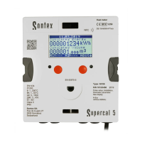
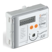
Display
The Supercal 739 LCD display has been designed to be large enough and per-
fectly readable by the user.
“Disabled” on the display means that the device is in the storage mode and
doesn’t count any Energy/Volume. In order to activate it refer to the User
Manual.
Mounting and metering activation procedure
1. Flush out the installation pipes carefully
2. Close the shutoff valves before and behind the meter.
3. Open the drainage valve to reduce the pressure and discharge the water
contained in the pipe.
4. Consider the direction of the flow
1. Place a gasket on each side of the flow meter. Only
use appropriate new gaskets.
2. Tighten the fixing nuts firmly by hand. Then tighten
up to the mechanical end stop using a mounting tool.
3. Turn the display into the desired position for reading.
4. Check the waterproofness of the meter placed under
pressure.
Coaxial multi jet meter with M77x1.5 connection
1. Remove the blind cover or the old meter from the
EAS base using an installation spanner.
2. Remove the pre-formed gasket then clean the
contact surfaces and the thread.
3. Place the new o-ring in the EAS base. Make sure
that the o-ring is correctly positioned.
4. Lubricate the external thread (M77x1.5’) of the
metering capsule with a fine silicone coating.
5. Lay the capsule in the base. Important! Make sure
that the blind hole in the metering capsule is cor-
rectly positioned in the base.
6. Screw the measuring capsule down firmly by hand,
then tighten as far as the mechanical end stop us-
ing a mounting tool.
Coaxial multi jet meter with G2’’ connection
1. Remove the blind cover or the old meter from the
EAS base using an installation spanner.
2. Remove the pre-formed gasket and then clean the
contact surfaces and the thread.
3. Place the new profiled gasket in the EAS base with
the plane surface facing upwards or the groove in
the preformed gasket facing downwards. Make sure
that the gasket is properly positioned.
4. Lubricate the external thread (G2’’) of the measur-
ing capsule with a fine silicone coating.
5. Screw the measuring capsule down firmly by hand.
Then tighten as far as the mechanical end stop us-
ing a mounting tool.
Coaxial multi jet meter with M62x2 connection
1. Remove the blind cover or the old meter from the
EAS base using an installation spanner.
2. Lubricate the external thread of the measuring
capsule with a fine silicone coating.
3. Screw the measuring capsule down firmly by hand.
Then tighten as far as the mechanical end stop us-
ing a mounting tool.
5. Turn the display into the desired position for reading.
6. Seal the flow meter, the measuring capsule and the temperature sensors.
When in storage mode (“Disabled” is displayed) activate the meter by long press-
ing the orange button (if config menu available, configure first).
CAUTION: this action is irreversible!
Declaration of conformity: The detailed certificate of
conformity can be consulted on the Sontex website:
www.sontex.ch or by scanning the following QR code:
 Loading...