EasyManua.ls Logo

Sony AV-3420CE - Page 7

Sony AV-3420CE
88 pages
Print Icon
To Next Page IconTo Next Page
To Previous Page IconTo Previous Page
Loading...
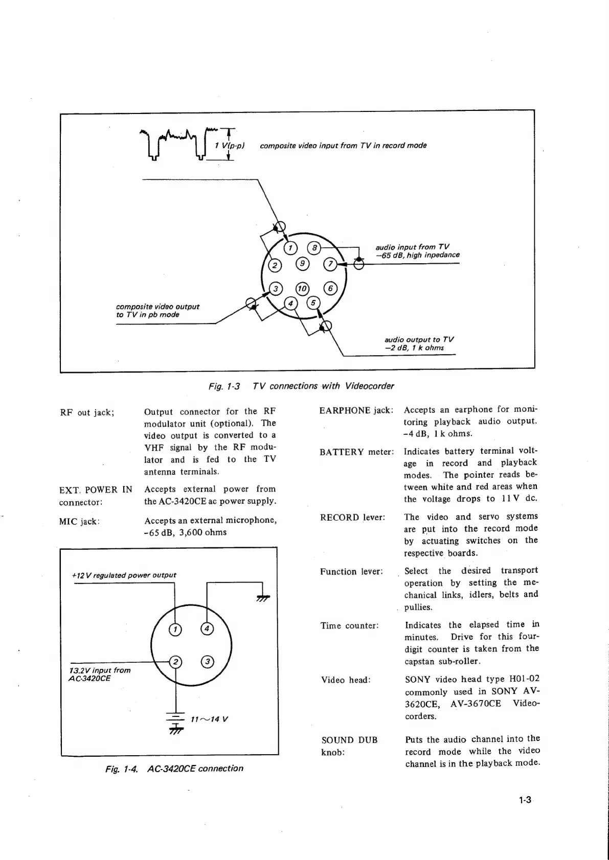
1
Vp-p)
composite
video
output
to
TV
in
pb
mode
RF
out
jack;
EXT.
POWER
IN
connector:
MIC
jack:
Fig.
1-3.
TV
connections
with
Videocorder
Output
connector
for
the
RF
modulator
unit
(optional).
The
video
output
is
converted
to
a
VHF
signal
by
the
RF
modu-
lator
and
is
fed
to
the
TV
antenna
terminals.
Accepts
external
power
from
the
AC-3420CE
ac
power
supply.
Accepts
an
external
microphone,
-65
dB,
3,600
ohms
+12
V
regulated
power
output
13.2V
input
from
AC-3420CE
Fig.
1-4.
AC-3420CE
connection
composite
video
input
from
TV
in
record
mode
audio input
from
TV
—65
dB,
high
inpedance
audio
output
to
TV
—2dB8,
1k
ohms
EARPHONE
jack:
BATTERY
meter:
RECORD
lever:
Function
lever:
Time
counter:
Video
head:
SOUND
DUB
knob:
_
Select
the
Accepts
an
earphone
for
moni-
toring
playback
audio
output.
-4dB,
1k
ohms.
Indicates
battery
terminal
volt-
age
in
record
and
playback
modes.
The
pointer
reads
be-
tween
white
and
red
areas
when
the
voltage
drops
to
11V
dc.
The
video
and
servo
systems
are
put
into
the
record
mode
by
actuating
switches
on
the
respective
boards.
desired
transport
operation
by
setting
the
me-
chanical
links,
idlers,
belts
and
.
pullies.
Indicates
the
elapsed
time
in
minutes.
Drive
for
this
four-
digit
counter
is
taken
from
the
capstan
sub-roller.
SONY
video
head
type
H01-02
commonly
used
in
SONY
AV-
3620CE,
AV-3670CE
Video-
corders.
Puts
the
audio
channel
into
the
record
mode
while
the
video
channel
is
in
the
playback
mode.
1-3