EasyManua.ls Logo

Sony AV-3420CE - Location of Parts and Controls

Sony AV-3420CE
88 pages
Print Icon
To Next Page IconTo Next Page
To Previous Page IconTo Previous Page
Loading...
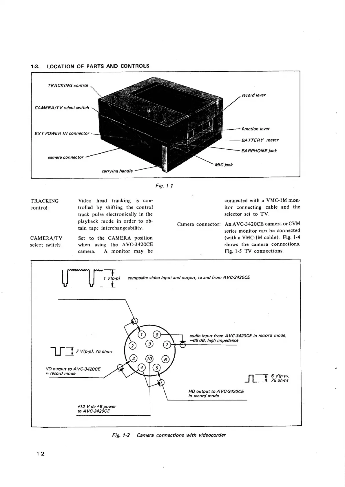
1-3.
LOCATION
OF
PARTS
AND
CONTROLS
TRACKING
control
CAMERA/TV
select
switch
EXT
POWER
IN
connector
camera
connector
TRACKING
control:
CAMERA/TV
select
switch:
carrying
handle
Video
head
tracking
is
con-
trolled
by
shifting
the
control
track
pulse
electronically
in
the
playback
mode
in
order
to
ob-
tain
tape
interchangeability.
Set
to
the
CAMERA
position
when
using
the
AVC-3420CE
camera.
A
monitor
may
be
1
Vip-p)
a
ee
7
Vip-p},
75
ohms
VD
output
to
AVC-3420CE
in
record
mode
+12
Vdc
+B
power
to
AVC-3420CE
Fig.
1-1
record
lever
function
lever
BATTERY
meter
EARPHONE
jack
MIC
jack
Camera
connector:
connected
with
a
VMC-1M
mon-
itor
connecting
cable
and
the
selector
set
to
TV.
An
AVC-3420CE
camera
or
CVM
series
monitor
can
be
connected
(with
a
VMC-1M
cable).
Fig.
1-4
shows
the
camera
connections,
Fig.
1-5
TV
connections.
composite
video
input
and
output,
to
and
from
AVC-3420CE
audio
input
from
AVC-3420CE
in
record
mode,
—65
dB,
high
impedance
6
Vip-p),
75
ohms
JIL
HD
output
to
AVC-3420CE
in
record
mode
Fig.
1-2
Camera
connections
with
videocorder