5-53
9. Hi8 REC L Level Adjustment (VC-215 board)
CCD-TR515E/TR516E/TR713E
CCD-TRV36E/TRV46E
Set the recording levels of the REC AFM signal and REC ATF sig-
nal. If the level is too low, the audio S/N will deteriorated, tracking
will not be stable, or SP/LP will not be discriminated properly. If
too high, color beets will be produced on the self-recording/play-
back image.
Mode VTR recording (SP mode)
Signal No signal
Measurement Point Pin !º of CN910 (REC RF)
Measuring Instrument Oscilloscope
(20MHz BW LIMIT: OFF)
Adjustment Page F
Adjustment Address 5B to 64
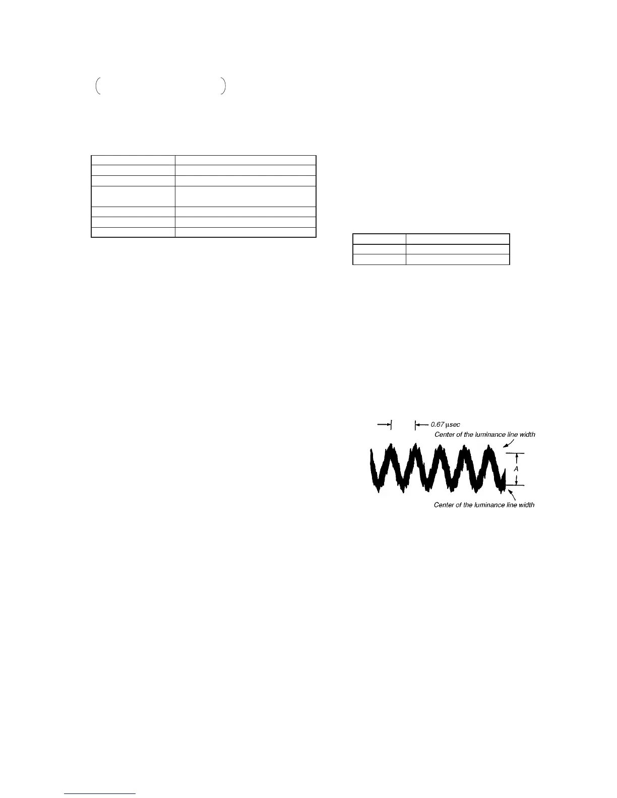
Specified Value A = 10.1±0.6mV
Connection:
1) Remove C085 (0.01µF, Pin !§ of IC202).
Note: After completing “REC L Level Adjustment” and “REC C
Current Adjustment”, replace C085 with new parts (1-162-
970-11 CERAMIC CHIP 0.01µF 10% 25V).
Adjusting method:
1) Insert Hi8 ME tape.
2) Select page: 0, address: 01, and set data: 01.
3) Select page: D, address: 14, after memorizing the data, set the
bit value of bit1 to “1”. (Refer to “3. Bit value discrimination”
of “3-1-8. Service mode”).
4) Select page: D, address: 15, after memorizing the data , set the
bit value of bit7 to “0”.
5) Set to recording mode. (Use the wireless remote commander
of 8mm VCR, or connect Pin 6 of CN935 of DD-117 board
and GND with 4.7kΩ registor for a second.)
4.7kΩ registor : 1-249-425-11
6) Insert Hi8 ME tape, set to recording mode.
7) Select page: 0, address: 01, and set data: 01.
8) Select page: F, address: 5B, set data: FF, and press the PAUSE
button of the adjusting remote commander.
9) Select page: F, address: 65, set data: 00, and press the PAUSE
button of the adjusting remote commander.
10) Select page: F, address: 5C, change the data and set the REC
AFM signal level (A) to the specified value.
11) Press the PAUSE button of the adjusting remote commander.
12) Select page: F, address: 5C, read the data (D5C).
Address Data
63 7A
64 7A
13) Calculate the adjustment data (hexadecimal) from the follow-
ing equations (hexadecimal calculation), and input each adjust-
ment address. (Refer to Table 5-1-2. Hexadecimal-Decimal
conversion Table.)
Address: 5B D5B = D5C
Address: 5D D5D = D5C
Address: 5E D5E = D5C
Address: 5F D5F = D5C + 12
Address: 60 D60 = D5C + 12
Address: 61 D61 = D5C + 12
Address: 62 D62 = D5C + 12
Note: After setting each data, be sure to press the PAUSE button
of the adjusting remote commander.
14) Write the following data in page: F, address: 63 to 64.
Note: After setting each data, be sure to press the PAUSE button
of the adjusting remote commander.
15) Select page: 0, address: 01, and set data: 00.
16) Perform “REC C Current Adjustment”.
17) Select page: 0, address: 01, and set data: 01.
18) Select page: D, address: 14, and set the data memorized.
19) Press the PAUSE button of the adjusting remote commander.
20) Select page: D, address: 15, and set the data memorized at step
4) of “Preparations only for the model without REC switch”.
21) Press the PAUSE button of the adjusting remote commander.
22) Select page: 0, address: 01, and set data: 00.
Fig. 5-3-14.