5-6
1-1-4. Precaution
1. Setting the Switch
Unless otherwise specified, set the switches as follows and perform
adjustments without loading cassette.
1. POWER switch (MA-345/346 board) ....................CAMERA
2. NIGHT SHOT switch (Lens Block)................................ OFF
3. DEMO MODE (Menu display)....................................... OFF
4. DIGITAL ZOOM (Menu display)................................... OFF
5. STEADY SHOT (Menu display) .................................... OFF
(TR713E/TRV46E)
6. DISPLAY (Menu display)................................. V-OUT/LCD
7. FOCUS switch (MF-8500).................................... MANUAL
8. PROGRAM AE (CF-60/61 board) ..................................Auto
9. BACK LIGHT (CF-60/61 board) .................................... OFF
10. PICTURE EFECT (CF-60/61 board) .............................. OFF
11. 16 : 9 WIDE (Menu display) ........................................... OFF
2. Adjusting Procedure
Adjust in the given order.
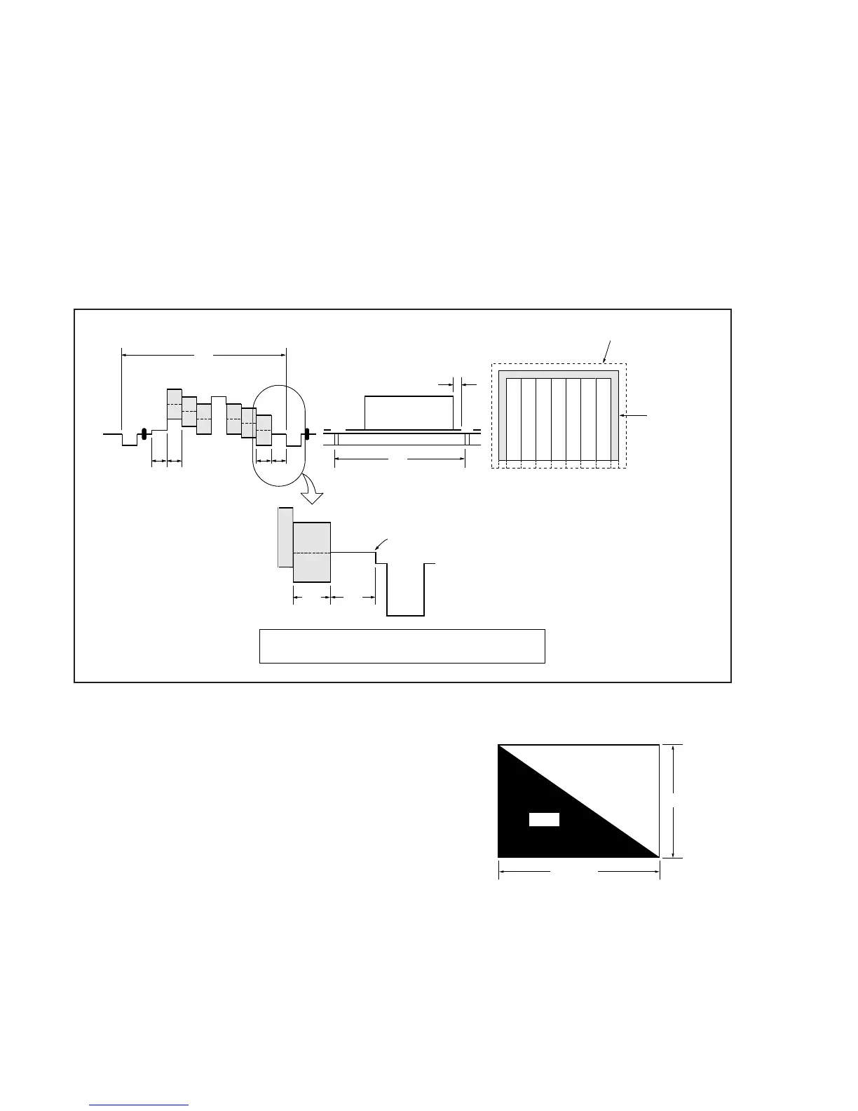
Fig. 5-1-5.
3. Subject
1) Color bar chart (Standard picture frame)
Adjust the picture frame as shown in Fig. 5-1-5. if adjustments
are performed using the color bar chart.
(Standard picture frame)
2) White pattern (Standard picture frame)
Remove the color bar chart from the pattern box, and insert a
clear chart in its place. (Do not perform zoom operations during
this time.)
3) Chart for flange back adjustment
Combine a white A0 size (1189 mm x 841 mm) paper to a black
one, and make the chart shown in Fig. 5-1-6.
Fig. 5-1-6.
Note : Use the non-reflecting and non-glazing vellum paper
whose size is more than A0, and make the boundary
between white and black to be smoothly flat.
Color bar chart standard picture trame
H
AB
A=B
B
A
0
±
0.1 msec
V
Enlargement
Difference in level
AB
Electronic beam
scanning frame
CRT picture fram