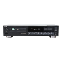
CDP-590
TABLE OF CONTENS
Section Title
Page
Specifications
1
1. GENERAL
4
2. iC FUNCTION DESCRIPTION
5
3. DISSASSEMBLY
OF BASE UNIT
6
4.
ADJUSTMENTS
7
5.
DIAGRAMS H
5-1.
Waveforms
11
5-2-
Printed Wiring
Boards 12
5-3.
Schematic Diagram
15
5-
4. IC
Block
Diagrams 19
6.
EXPLODED VIEWS 21
6-
1. Cabinet
Section
21
6-2.
Front Panel Section
22
6-3.
MD Section-KCDM
L4-5RD1)
23
6-4.
MD Section-2(BU-5BDl)
24
7.
ELECTRICAL PARTS LIST
25
SUPPLEMENT-1
(AEP and UK
Model)
3.
Measuring the voltage
drop
across a resistor by
means of a
VOM
or battery-operated AC
volt-
meter. The
“limit” indication is
0.75V, so
analog meters must have
an
accurate
low-
voltage scale. The
Simpson 250 and
Sanwa
SH-63Trd are
examples of
a
passive VOM that
is suitable.
Nearly all battery
operated
digital
multimeters that
have
a 2V AC range are
suitable.
(See Fig.
A)
To Exposed
Metal
Parts on Set
0
. 15
;^
-r-
Earth Ground
AC
voltmeter
(0.75V)
Fig. A. Using an AC
voltmeter to check AC leakage.
SAFETY
CHECK-OUT
After
correcting the original
service problem,
perform
the following safety
check before releasing
the set to the
customer:
Check the antenna
terminals, metal trim,
“metallized”
knobs, screws,
and all other exposed
metal parts for
AC leakage.
Check leakage
as described below.
LEAKAGE
TEST
The AC leakage
from any
exposed metal part to
earth ground and
from all
exposed
metal
parts to any
exposed metal
part having a
return to chassis, must
not exceed
0.5 mA
(500
microampers).
Leakage
current
can be measured
by
any
one of three
methods.
1
. A
commercial
leakage tester,
such as the
Simpson 229 or
RCA
WT-S40A.
Follow the
manufacturers’
instructions to
use these instru-
ments.
2. A battery-operated
AC
milliammeter. The Data
Precision
245 digital multimeter is
suitable for
this job.
SERVICING NOTE
NOTES ON HANDLING THE OPTICAL PICK-
UP
BLOCK OR BASE UNIT
The
laser
diode
in the optical
pick-up block may
suffer electrostatic breakdown
because of the
poten-
tial difference generated
by the charged electrostatic
load, etc. on clothing and the human
body.
During repair,
pay
attention
to electrostatic break-
down and also use the procedure
in the
printed
matter which
is included in the repair
parts.
The flexible board is easily damaged
and should be
handled with care.
CAUTION
Use of controls or adjustments or performance
of
procedures other than those specified herein
may
result in hazardous radiation exposure.
NOTES ON LASER DIODE EMISSION CHECK
The
laser beam on this model is concentrated
so
as to be
focused on the disc reflective surface by the objective
lens in the optical pick-up block. Therefore, when check-
ing the laser diode emission, observe
from more than 30
cm away from the objective lens.
-2