EasyManua.ls Logo

Sony CDP-561 - Service Manual

Sony CDP-561
25 pages
Print Icon
To Next Page IconTo Next Page
Loading...
CDP-961/961E
SERVICE
MANUAL
AEP
Mode!
CDP-561
UK
Model
CDP-561E
Photo
:
CDP-561
Model
Name
Using
Similar
Mechanism
|
CDP-715/715E
CD
Mechanism
Type
CDM25D-5BD20
Base
Unit
Type
BU-5BD20
Optical
Pick-up
Type
KSS-213BA
SPECIFICATIONS
Compact
disc
player
General
Laser
Semiconductor
laser
Power
requirements
220
V
-
230
V
AC,
50/60
Hz
Wavelength
780
—-
790
nm
Power
consumption
13
W
Frequency
response
2
Hz
to
20
kHz
+
0.5
dB
Dimensions
(approx.)
430
x
110
x
295
mm
Signal-to-noise
ratio
More
than
108
dB
(w/h/d)
(17
x
43/8
x
11
5/8
in.)
incl.
projecting
Dynamic
range
More
than
99
dB
pee
Harmonic
distortion
Less
than
0.0027%
Massilappiox:)
Senos
Channel
separation
More
than
103
dB
Supplied
accessories
Outputs
Audio
cord
(2
phono
plugs
~
2
phono
plugs)
(1)
Jack
Maximum
Load
Sony
SUM-3
(NS)
batteries
(2)
type
output
impedance
level
Design
and
specifications
are
subject
to
change
without
notice.
LINE
OUT
Phono
2V
Over
10
kilohms
(FIXED)
jacks
(at
50
kilohms)
LINE
OUT
Phono
2V
Over
50
kilohms
(VARIABLE)
jacks
(at
50
kilohms)
DIGITAL
Optical
-18dBm
Wave
length:
660
nm
OUT
output
(OPTICAL)
connector
PHONES
Stereo
-
10mW
32
ohms
phone
=
COMPACT
DISC
PLAYER
SONY.

Other manuals for Sony CDP-561

Question and Answer IconNeed help?

Do you have a question about the Sony CDP-561 and is the answer not in the manual?

Sony CDP-561 Specifications

General IconGeneral
BrandSony
ModelCDP-561
CategoryCD Player
LanguageEnglish

Summary

CD Player Specifications

General Specifications

Power, dimensions, mass, and general characteristics of the CD player.

Disc Playback Performance

Laser, frequency response, SNR, dynamic range, and distortion specifications.

Output Interface Details

Line out, digital out, and headphone output specifications.

Safety and Model Identification

Laser Safety Warnings

Critical safety information regarding laser exposure.

Model Identification Guide

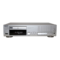
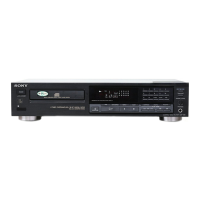
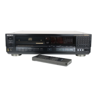
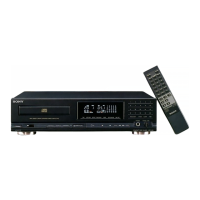
Information for distinguishing between different product models.

Section 1: Servicing Notes

Optical Pick-up and Laser Diode Handling

Safe handling guidelines and diagnostic checks for optical components.

Section 2: General Information

Component Identification

Visual guide to unit controls and remote commander buttons.

Section 3: Disassembly Procedures

Loading Panel and Mechanism Block Removal

Step-by-step guide for disassembling key internal components.

Section 4: Electrical Diagnostics

Signal Waveform and Balance Checks

Procedures for S-curve, E-F balance, and RF level checks.

RF PLL Frequency Verification

Procedure to confirm the RF PLL free-run frequency.

Circuit Board Adjustment Locations

Diagrams indicating points for internal adjustments.

Section 5: IC Pin Function Details

CXD2545 Q IC Pinout

Detailed pin function descriptions for the CXD2545Q integrated circuit.

CXP82316-055 Q IC Pinout

Detailed pin function descriptions for the CXP82316-055Q integrated circuit.

Section 5: Circuit Board Locations

Component Placement Diagrams

Visual overview of circuit board placement within the unit.

Section 5: Printed Wiring Board Diagrams (BD)

BD Board Component Layout

Visual representation of component placement on the BD board.

Section 5: Schematic Diagrams (BD)

BD Board Circuit Schematics

Detailed electrical schematics for the BD board.

Section 5: Schematic Diagrams (Main)

Main Board Circuit Schematics

Detailed electrical schematics for the Main board.

Section 5: Printed Wiring Board Diagrams (Main)

Main Board Component Layout

Visual representation of component placement on the Main board.

Section 6: Exploded Views

Case and Front Panel Assembly

Exploded diagram showing chassis and front panel components.

Chassis Section Components

Exploded diagram detailing chassis components.

Mechanism Section (CDM25 D-5 BD20)

Exploded view of the CD mechanism assembly.

Base Unit Section (BU-5 BD20)

Exploded view of the base unit assembly.

Section 7: Electrical Parts List

Component Breakdown by Board

Comprehensive list of electronic components for each board.

Related product manuals