TABLE
OF CONTENTS
Section Page
I.
GENERAL
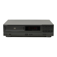
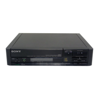
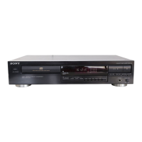
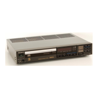
1-1. Partsldentification
.
......3
2. TEST MODES
2-1.
Test Mode
of Display
Microcomputer
(IC401)
....4
2-2. Test Mode
of
CD
System Controller
(1C202)
.. . .
..4
3. ELECTRICAL BLOCK
CHECKING
.........5
4. DIAGRAMS
4-1.
PinDescription.... .......7
4-2. BlockDiagram....
.......9
4-3.
PrintedWiringBoards
..........12
4-4. Schematic Diagram
.......15
4-5.
Semiconductor Lead
Layouts
...........22
5. EXPLODED VIETYS
5-1. Chassis
..........23
5-2.
CD Block
(CDM13BA-58D3)
.. . ...
. . ...24
5-3.
Optical
Pick-Up Block
(BU-5BD3)
. . . ...
. ...
...
.25
6. ELECTRICAL PARTS LIST
........26
NOTES
ON
HANDLING THE
OPTICAL
PICK.UP
BLOCK
OR
BASE
UNIT
The laser
diode
in the optical
pick-up
block may
suffer
electrostatic
breakdown
because of
the
potential
diference
generated
by the charged electrostatic load,
etc.
on
clothing
and the
human
body.
During repair,
pay
attention to
electrostatic breakdown
and
also
use
the
procedure
in
the
printed
matter which
is
included
in the repair
parts.
The flexible
board
is
easily damaged and
should be
handled
with
care.
NOTES ON LASER DIODE EMISSION
CHECK
The laser
beam
on
this model is concentrated so
as to be
focused
on
the
disc reflective surface
by the
objective
lens
in
the
optical
pick-up
block. Therefore, when checking
the
laser
diode emission, observe from more than 30cm
away from
the
objective
lens.
LASER DIODE
AND FOCUS
SERCH OPERATION
CHECK
1. Make POWER
switch on
with no
disc
inserted
and disc
table closed.
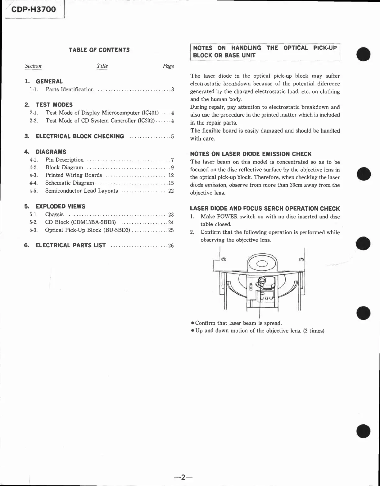
2.
Confirm that
the
following
operation is
performed
while
observing
the
objective
lens.
oConfirm
that
laser
beam is
spread.
o
Up
and down motion
of
the
objective
lens.
(3
times)
Title
-2-