EasyManua.ls Logo

Sony CDP-X559ES - Electrical Block Checking

Sony CDP-X559ES
31 pages
Print Icon
To Next Page IconTo Next Page
To Previous Page IconTo Previous Page
Loading...
CDP-X559ES
SECTION
2
ELECTRICAL
BLOCK
CHECKING
Note:
1.
CD
Block
basically
constructed
to
operate
without
adjus-
tment.
Therefore,
check
each
item
in
order
given.
2.
Use
YEDS-18
disc
(3-702-101-01)
unless
otherwise
indicat-
ed.
3.
Use
the
oscilloscope
with
more
than
10MQ
impedance.
4.
Clean
an
object
lens
by
an
applicator
with
neutral
deter-
gent
when
the
signal
level
is
low
than
specified
value
with
the
following
checks.
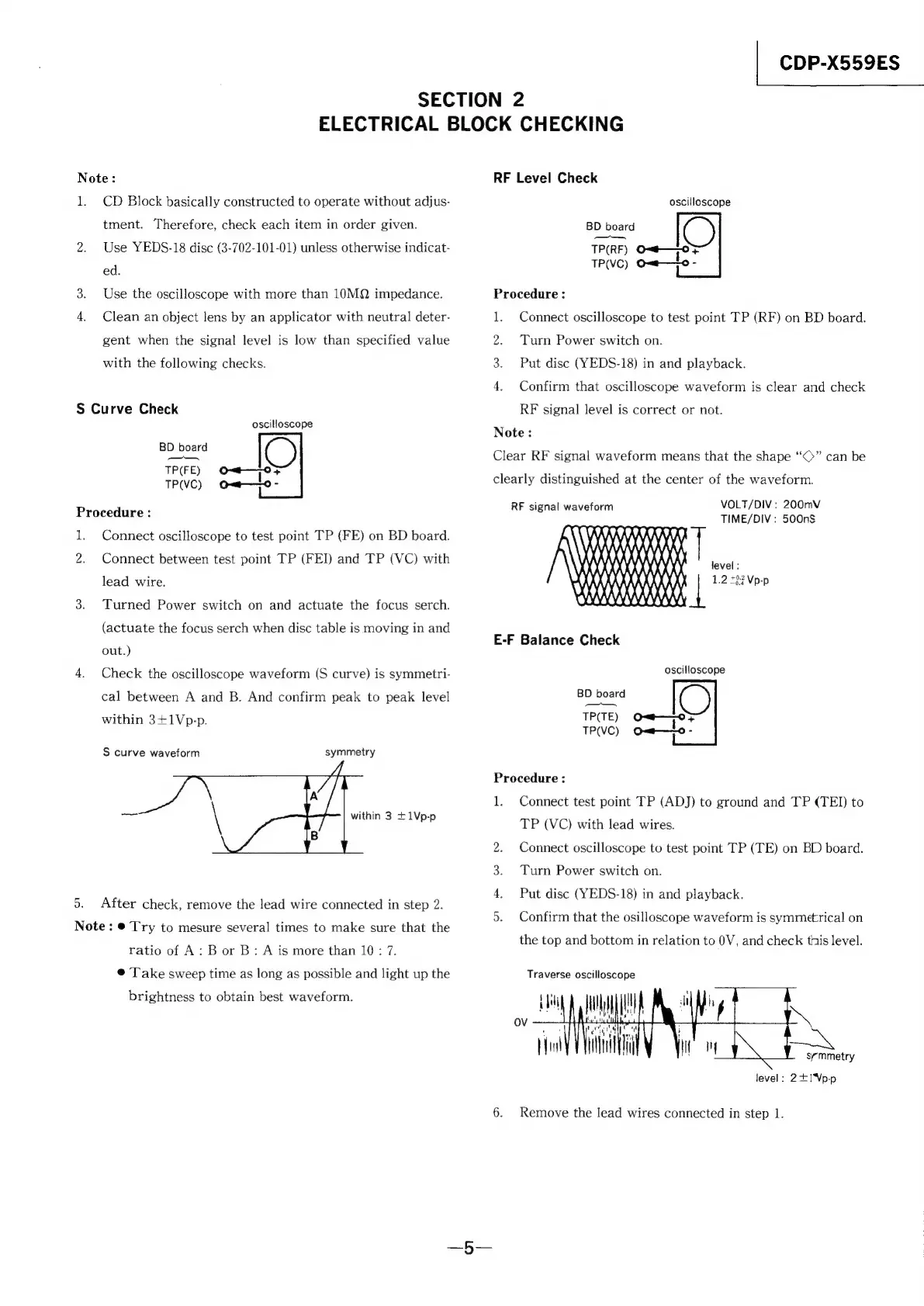
S
Curve
Check
oscilloscope
BD
board
ee
—__—_—_
TP(FE)
Ot
°F
TP(VC)
Q=t———-0
-
Procedure
:
1.
Connect
oscilloscope
to
test
point
TP
(FE)
on
BD
board.
2.
Connect
between
test
point
TP
(FEI)
and
TP
(VC)
with
lead
wire.
3.
Turned
Power
switch
on
and
actuate
the
focus
serch.
(actuate
the
focus
serch
when
disc
table
is
moving
in
and
out.)
4.
Check
the
oscilloscope
waveform
(S
curve)
is
symmetri-
cal
between
A
and
B.
And
confirm
peak
to
peak
level
within
3+1Vp-p.
S
curve
waveform
symmetry
within
3
+1Vp-p
5.
After
check,
remove
the
lead
wire
connected
in
step
2.
Note:
©
Try
to
mesure
several
times
to
make
sure
that
the
ratio
of
A:
B
or
B:
A
is
more
than
10:
7.
©
Take
sweep
time
as
long
as
possible
and
light
up
the
brightness
to
obtain
best
waveform.
RF
Level
Check
oscilloscope
BD
board
(>
—_—
TP(RF)
Onc
+
TP(VC)
=
Procedure:
1.
Connect
oscilloscope
to
test
point
TP
(RF)
on
BD
board.
2.
Turn
Power
switch
on.
3.
Put
disc
(YEDS-18)
in
and
playback.
4.
Confirm
that
oscilloscope
waveform
is
clear
and
check
RF
signal
level
is
correct
or
not.
Note:
Clear
RF
signal
waveform
means
that
the
shape
“©”
can
be
clearly
distinguished
at
the
center
of
the
waveform.
VOLT/DIV
:
200mV
TIME/DIV:
500nS
RF
signal
waveform
\
WV
KAAAAKAAK}
\
HAN
|
AHH
tN
WAN
level
:
1.2
707
Vp-p
E-F
Balance
Check
oscilloscope
BD
board
CS)
TP(TE)
O=—=-———o>
TP(VC)
ow—lo
2
Procedure
:
1.
Connect
test
point
TP
(ADJ)
to
ground
and
TP
(TEI)
to
TP
(VC)
with
lead
wires.
Connect
oscilloscope
to
test
point
TP
(TE)
on
BD
board.
Turn
Power
switch
on.
Put
disc
(YEDS-18)
in
and
playback.
Confirm
that
the
osilloscope
waveform
is
symmetrical
on
BPE
OR?
TS
the
top
and
bottom
in
relation
to
0V,
and
check
this
level.
Traverse
oscilloscope
Ua
(
symmetry
level:
2+1Vp-p
6.
Remove
the
lead
wires
connected
in
step
1.