EasyManua.ls Logo

Sony CDP-XE900 Service Manual

Sony CDP-XE900
27 pages
To Next Page IconTo Next Page
Page #1 background imageLoading...
Page #1 background image
— 1 —
Model Name Using Similar Mechanism NEW
CD Mechanism Type CDM36-14
Base Unit Type BU-14
Optical Pick-up Type KSS-213B/S-N
SPECIFICATIONS
MICROFILM
COMPACT DISC PLAYER
AEP Model
CDP-XE900
UK Model
Chinese Model
CDP-XE900E
Compact disc player
Laser Semiconductor laser (λ = 780 nm)
Emission duration: continuous
Laser output Max 44.6 µW*
* This output is the value measured at
a distance of 200 mm from the
objective lens surface on the Optical Pick-
up block with 7 mm aperture.
Frequency response 2 Hz to 20 kHz ± 0.5 dB
Signal-to-noise ratio More than 113 dB
Dynamic range More the 99 dB
Harmonic distortion Less than 0.0025%
Channel separation More than 105 dB
General
Power requirements Except Chinese model :
220 V – 230 V AC, 50/60 Hz
Chinese model : 220V AC50/60Hz
Power consumption 14W
Dimensions (approx.) 430 × 1107 × 295 mm
(w/h/d) (17 × 4 1/4 × 11 5/8 in.) incl. projecting
parts
Mass (approx.) 5.2 kg (8 lbs 13 oz)
Supplied accessories
Audio cord (2 phono plugs–2 phono plugs) (1)
Remote commander (RM-D820) (1)
Sony SUM-3 (NS) batteries (2)
Design and specifications are subject to change without notice.
PHOTO : CDP-XE900
CDP-XE900/XE900E
SERVICE MANUAL
Outputs
Jack Maximum Load
type output impedance
level
LINE OUT Phono 2 V Over 50 kilohms
jacks (at 50 kilohms)
DIGITAL Optical –18 dBm Wave length : 660 nm
OUT output
(OPTICAL) connector
PHONES Stereo 10 mW 32 ohms
(CDP-XE900) phone
jack
w
w
w
.
x
i
a
o
y
u
1
6
3
.
c
o
m
Q
Q
3
7
6
3
1
5
1
5
0
9
9
2
8
9
4
2
9
8
T
E
L
1
3
9
4
2
2
9
6
5
1
3
9
9
2
8
9
4
2
9
8
0
5
1
5
1
3
6
7
3
Q
Q
TEL 13942296513 QQ 376315150 892498299
http://www.xiaoyu163.com
Question and Answer IconNeed help?

Do you have a question about the Sony CDP-XE900 and is the answer not in the manual?

Sony CDP-XE900 Specifications

General IconGeneral
BrandSony
ModelCDP-XE900
CategoryCD Player
LanguageEnglish

Summary

SERVICE MANUAL

Specifications

Lists technical specifications like laser output, frequency response, and power requirements.

CAUTION

Notes on chip component replacement

Guidelines for replacing chip components, including caution for tantalum capacitors.

Flexible Circuit Board Repairing

Instructions for repairing flexible circuit boards, focusing on soldering techniques and heat.

SAFETY-RELATED COMPONENT WARNING !!

Warning about safety-critical components and the need for specific replacement parts.

MODEL IDENTIFICATION

SECTION 1 SERVICING NOTE

HOW TO OPEN THE DISC TRAY WHEN POWER SWITCH TURNS OFF

Step-by-step guide to manually open the disc tray when the power is off.

NOTES ON HANDLING THE OPTICAL PICK-UP BLOCK OR BASE UNIT

Precautions for handling the optical pick-up block to prevent electrostatic breakdown.

NOTES ON LASER DIODE EMISSION CHECK

Guidelines for safely checking laser diode emission, emphasizing safe viewing distances.

LASER DIODE AND FOCUS SEARCH OPERATION CHECK

Procedure for checking laser diode and focus search operations using an S-curve waveform.

SECTION 2 GENERAL

LOCATION OF PARTS AND CONTROLS - Front Panel

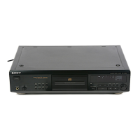
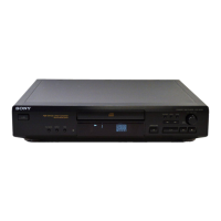
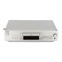
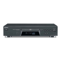
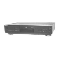
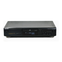
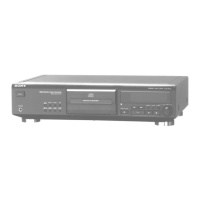
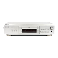
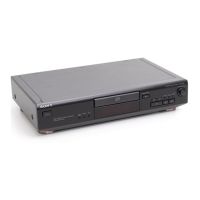
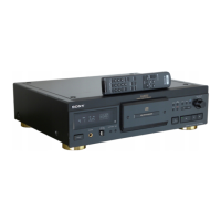
Identifies and labels all controls and parts on the front panel of the unit.

SECTION 3 DISASSEMBLY

FRONT PANEL ASSEMBLY

Detailed steps for removing and disassembling the front panel assembly.

SECTION 4 TEST MODE

AF MODE

Details the AF mode for performing checks like FL tube, key, and remote commander checks.

ADJ MODE

CLV-S MODE

Describes the CLV-S mode for spindle servo operations during playback.

TABLE OF BUTTON OPERATIONS IN ADJ MODE

Lists functions of number buttons when used with the remote commander in ADJ mode.

SECTION 5 ELECTRICAL BLOCK CHECKING

S Curve Check

Procedure for checking the S-curve waveform to verify optical pick-up performance.

E-F Balance (1 Track Jump) Check

Method to check E-F balance by analyzing a 1-track jump waveform.

RF Level Check

Procedure to check the RF signal level and waveform clarity.

E-F Balance (Traverse) Check

Method to check E-F balance in traverse mode, involving tracking and sledding servos.

RF PLL Free-run Frequency Check

SECTION 6 DIAGRAMS

CIRCUIT BOARDS LOCATION

Shows the physical layout and placement of all circuit boards within the unit.

SCHEMATIC DIAGRAM - MAIN SECTION

PRINTED WIRING BOARD - MAIN SECTION

Printed wiring board layout for the main section.

SCHEMATIC DIAGRAM - BD SECTION

PRINTED WIRING BOARD - BD SECTION

Printed wiring board layout for the BD section.

IC PIN FUNCTION

PRINTED WIRING BOARD - BD SECTION

IC Block Diagrams

Block diagrams for key ICs like CXD2545Q and CXA1821M.

SECTION 7 EXPLODED VIEWS

CASE SECTION

Exploded view and parts list for the case section of the unit.

CHASSIS SECTION

CD MECHANISM SECTION (CDM36-14)

BASE UNIT SECTION (BU-14)

SECTION 8 ELECTRICAL PARTS LIST

< CAPACITOR >

Lists various ceramic, tantalum, and electrolytic capacitors with their specifications.

< DIODE >

Lists diodes used in the circuit with their part numbers and types.

< IC >

Lists integrated circuits used in the unit with their part numbers.

< RESISTOR >

< SWITCH >

Lists various types of switches used in the unit.

< CONNECTOR >

< TRANSISTOR >

Lists transistors used in the circuit with their part numbers.

< GROUND TERMINAL >

< VIBRATOR >

Lists the crystal vibrator component used for clock generation.

TRANS

< TRANSFORMER >

Details the power transformer used in the unit.

MISCELLANEOUS

Lists various miscellaneous parts, wires, and adapters.

ACCESSORIES & PACKING MATERIALS

Lists accessories, manuals, and packing materials included with the product.

Related product manuals