Do you have a question about the Sony CDP-XE570 and is the answer not in the manual?
General specifications like power requirements, dimensions, and mass.
Technical performance details of the CD player, including laser, frequency response, dynamic range, and distortion.
Details of analog and digital audio outputs, jack types, output levels, and impedances.
Guidelines for handling components, circuit boards, and safety warnings.
Warning about components critical for safe operation and replacement.
Procedure for manually opening the disc tray without power.
Precautions for safe handling of the optical pick-up block to prevent damage.
Instructions for safely checking laser diode emission.
Procedure for using the CD-TEXT TEST DISC to verify display functionality.
Table listing the text data content for the CD-TEXT TEST DISC.
Table correlating recorded CD-TEXT content with unit display, including character handling.
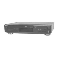
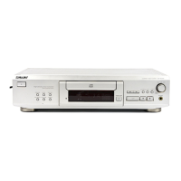
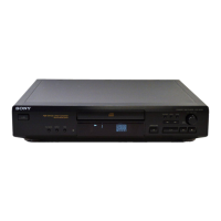
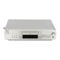
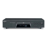
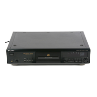
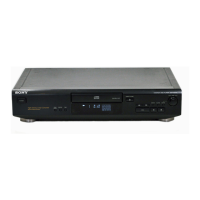
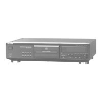
Identification and description of front panel buttons, indicators, and jacks.
Identification of rear panel connectors, including analog and digital outputs.
Steps for removing the loading panel from the unit.
Instructions for disassembling and removing the base unit.
Detailed procedures for performing offset and RFDC value checks.
Procedures for FL tube, key, and remote commander checks in AFADJ mode.
Explanation of button operations and functions within the ADJ mode.
Procedure for measuring RF signal levels using an oscilloscope.
Procedure for checking E-F balance and servo performance.
Diagram indicating test points on the display board for adjustments.
Diagram indicating test points on the BD board for adjustments.
Diagram showing the location and names of all internal circuit boards.
Schematic diagram of the loading motor control circuitry.
Printed wiring board layout for the loading motor section.
Printed wiring board layout for the BD board, Side A.
Printed wiring board layout for the BD board, Side B.
Detailed schematic diagram for the BD board, showing IC interconnections.
Printed wiring board layout for the main board, including associated boards.
Schematic diagram for the main board, illustrating major ICs and circuits.
Printed wiring board layout for the display board and key board.
Schematic diagram for the display board, showing IC connections and button inputs.
Detailed list of pin names and functions for the IC501 Master Control IC.
Block diagram illustrating the functional blocks within IC101.
Circuit diagram for IC131, showing internal signal paths and components.
Exploded view of the front panel and case with parts list.
Exploded view of the CD mechanism, showing its components.
Detailed exploded view and parts list for the CD mechanism.
Detailed exploded view and parts list for the base unit.
List of capacitors and resistors on the BD board with their specifications.
List of semiconductors and connectors on the BD board.
Parts list for Display, Headphone, and Key boards, including resistors, capacitors, and ICs.
List of capacitors for the Main and Power SW boards with specifications.
List of connectors, switches, and diodes for Main and Power SW boards.
List of resistors for the Main and Power SW boards with specifications.
List of hardware, accessories, and packing materials.
History of revisions made to the service manual.
| Type | CD Player |
|---|---|
| Channels | 2 |
| Frequency Response | 2 Hz - 20 kHz |
| Signal-to-Noise Ratio | 110 dB |
| Dynamic range | 100 dB |
| Digital Output | Coaxial |
| Output Voltage | 2 V |
| Power Consumption | 15 W |
| Disc format | CD |
| Line output | 2V |