EasyManua.ls Logo

Sony CDP-XE270 Service Manual

Sony CDP-XE270
42 pages
To Next Page IconTo Next Page
Page #1 background imageLoading...
Page #1 background image
SERVICE MANUAL
COMPACT DISC PLAYER
US Model
AEP Model
UK Model
E Model
Australian Model
CDP-XE270/XE370
Canadian Model
CDP-XE270
SPECIFICATIONS
CDP-XE270/XE370
Photo: CDP-XE370
Ver. 1.4 2006.07
Model Name Using Similar Mechanism NEW
CD Mechanism Type CDM66-5BD27
Base Unit Name BU-5BD27
Optical Pick-up Name PXR-104X or KSS-213C
Compact disc player
Laser Semiconductor laser (λ =
780 nm)
Emission duration:
continuous
Frequency response 2 Hz to 20 kHz ± 0.5 dB
Dynamic range More than 93 dB
Harmonic distortion 0.0045%
Outputs
ANALOG
OUT
DIGITAL
OUT
(OPTICAL)
General
Power consumption 11 W
Dimensions (approx.) 430 x 95 x 290 mm
(w/h/d) incl. projecting parts
Mass (approx.)
CDP-XE370: 3.2 kg
CDP-XE270: 3.2 kg
Supplied accessories
Audio cord (2 phono plugs – 2 phono plugs) (1)
Remote commander (remote) (1) (CDP-XE370 only)
R6 (size AA) batteries (2) (CDP-XE370 only)
Design and specifications are subject to change
without notice.
Load
impedance
Over 10
kilohms
Wave length:
660 nm
Jack
type
Phono
jacks
Optical
output
connector
Maximum
output level
2 V
(at 50
kilohms)
–18 dBm
Power requirements
Where purchased
US, Canadian models
AEP, UK models
Australian model
Singapore model
Power requirements
120 V AC, 60 Hz
230 V AC, 50/60 Hz
240 V AC, 50/60 Hz
220 V– 230 V AC, 50/60 Hz
9-929-591-15 Sony Corporation
2006G05-1 Home Audio Division
© 2006.07 Published by Sony Techno Create Corporation
Question and Answer IconNeed help?

Do you have a question about the Sony CDP-XE270 and is the answer not in the manual?

Sony CDP-XE270 Specifications

General IconGeneral
BrandSony
ModelCDP-XE270
CategoryCD Player
LanguageEnglish

Summary

SPECIFICATIONS

SECTION 1 SERVICING NOTES

MODEL IDENTIFICATION

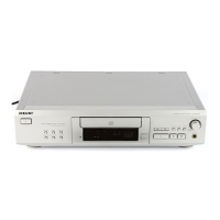
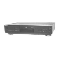
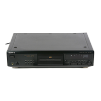
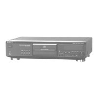
Identifies different product models and their corresponding part numbers.

SECTION 2 GENERAL

LOCATION OF CONTROLS

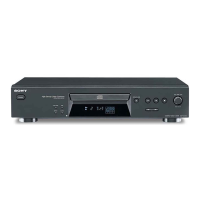
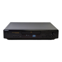
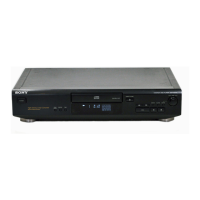
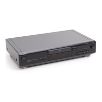
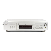
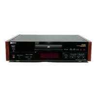
Details the location of all controls and indicators on the front and rear panels.

SECTION 3 DISASSEMBLY

DISASSEMBLY PROCEDURES

Step-by-step guide covering disassembly flow, case, mechanism deck, main board, and base unit.

SECTION 4 TEST MODE

TEST MODES OPERATION

Procedures for operating the unit in Aging, Check, ADJ, and AFADJ test modes.

SECTION 5 ELECTRICAL CHECKS

PERFORMANCE CHECKS

Instructions for S Curve, RFDC, RFAC level checks, and E-F Balance check.

SECTION 6 DIAGRAMS

DIAGRAM INTERPRETATION AND BOARD LAYOUTS

Notes on diagram conventions and component layouts for various boards.

SCHEMATIC DIAGRAMS AND IC DESCRIPTIONS

Electrical schematics for main boards and detailed IC pin function descriptions.

SECTION 7 EXPLODED VIEWS

ASSEMBLY VIEWS

Exploded views illustrating the assembly of case, front panel, mechanism deck, and base unit.

SECTION 8 ELECTRICAL PARTS LIST

Related product manuals