EasyManua.ls Logo

Sony CDP-XE700 Service Manual

Sony CDP-XE700
25 pages
To Next Page IconTo Next Page
Page #1 background imageLoading...
Page #1 background image
— 1 —
Model Name Using Similar Mechanism CDP-XE800
CD Mechanism Type CDM36-14
Base Unit Type BU-14
Optical Pick-up Type KSS-213B/S-N
SPECIFICATIONS
MICROFILM
COMPACT DISC PLAYER
CDP-XE700
AEP Model
UK Model
Compact disc player
Laser Semiconductor laser (λ = 780 nm)
Emission duration: continuous
Laser output Max 44.6 µW*
* This output is the value measured at
a distance of 200 mm from the
objective lens surface on the Optical Pick-
up block with 7 mm aperture.
Frequency response 2 Hz to 20 kHz ± 0.5 dB
Signal-to-noise ratio More than 102 dB
Dynamic range More the 98 dB
Harmonic distortion Less than 0.0035%
Channel separation More than 100 dB
General
Power requirements 220 V – 230 V AC, 50/60 Hz
Power consumption 12W
Dimensions (approx.) 430 × 1107 × 295 mm
(w/h/d) (17 × 4 1/4 × 11 5/8 in.) incl. projecting
parts
Mass (approx.) 3.6 kg (7 lbs 15 oz)
Supplied accessories
Audio cord (2 phono plugs–2 phono plugs) (1)
Remote commander (RM-D820) (1)
Sony SUM-3 (NS) batteries (2)
Design and specifications are subject to change without notice.
PHOTO : AEP model
SERVICE MANUAL
Outputs
Jack Maximum Load
type output impedance
level
LINE OUT Phono 2 V Over 50 kilohms
jacks (at 50 kilohms)
DIGITAL Optical –18 dBm Wave length : 660 nm
OUT output
(OPTICAL) connector
PHONES Stereo 10 mW 32 ohms
phone
jack
Question and Answer IconNeed help?

Do you have a question about the Sony CDP-XE700 and is the answer not in the manual?

Sony CDP-XE700 Specifications

General IconGeneral
BrandSony
ModelCDP-XE700
CategoryCD Player
LanguageEnglish

Summary

Servicing Notes and Procedures

Servicing Procedures and Precautions

Essential notes for handling optical pick-up, laser diode, and disc tray operation during service.

General Information

Location of Parts and Controls

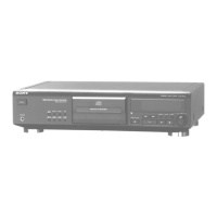
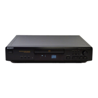
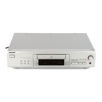
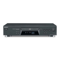
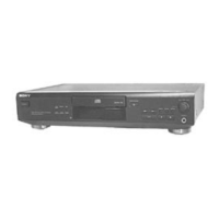
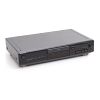
Identifies and locates the external controls and parts on the front panel of the CDP-XE700.

Disassembly Instructions

Front Panel Assembly Disassembly

Detailed steps for the safe and correct disassembly of the front panel unit.

Test Mode Operations

AF Mode Testing Procedures

Guides for performing various functional checks using the AF mode, including FL tube and key checks.

ADJ and CLV-S Mode Operations

Instructions for operating the unit in ADJ mode for adjustments and CLV-S mode for spindle servo playback.

Electrical Block Checking

S Curve and RF Level Electrical Checks

Procedures for verifying S-curve symmetry and RF signal levels using test points and an oscilloscope.

E-F Balance Electrical Checks

Steps to check E-F balance with and without the remote commander for proper operation.

RF PLL Free-run Frequency Check

Procedure to measure and verify the RF PLL free-run frequency using a frequency counter.

Diagrams and Schematics

Circuit Boards Location Diagram

Visual guide to the placement of all circuit boards within the CDP-XE700.

IC Pin Function Details

Comprehensive listing of pin functions for key integrated circuits, including system control ICs.

Printed Wiring Board Layout - BD Section

Detailed layout of components and traces for the BD section's printed wiring board.

Schematic Diagram - BD Section

Complete circuit schematic detailing the electrical connections for the BD section.

Printed Wiring Board Layout - Main Section

Detailed layout of components and traces for the Main section's printed wiring board.

Schematic Diagram - Main Section

Complete circuit schematic detailing the electrical connections for the Main section.

Exploded Views

Front Panel Section Exploded View

Visual representation of the front panel assembly, showing all parts and their relationships.

Chassis Section Exploded View

Exploded diagram of the main chassis, detailing the arrangement of internal components.

CD Mechanism Section Exploded View

Detailed exploded view of the CDM36-14 CD mechanism, listing all constituent parts.

Base Unit Section Exploded View

Exploded diagram of the BU-14 base unit, illustrating component assembly and identification.

Electrical Parts List

Related product manuals