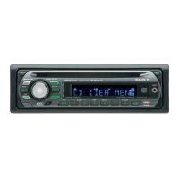
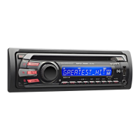
CDX-GT35UW
24
• IC Pin Function Description
MAIN BOARD (2/3) IC401 MB90F882PF-G-103JNE1 (SYSTEM CONTROL)
Pin No. Pin Name I/O Description
1 CYRIL_SEL I Cyril select signal input (L: No cyril select)
2 B-OUT_SEL I Black out setting signal input (L: No black out)
3 COL_SW_SEL I Key illumination initial color setting signal input (L: Amber)
4 ILLUMI_SEL I Key illumination voltage setting signal input (H: 10.4 V)
5, 6 NCO O Not used. (Open)
7
NOSE_SW I Front panel detach detect signal input
8 to 10 NCO O Not used. (Open)
11 RE_IN0 I Rotary encoder signal input 0
12 RE_IN1 I Rotary encoder signal input 1
13 X_OUT O Low speed operation clock signal output (32.768 kHz)
14 X_IN I Low speed operation clock signal input (32.768 kHz)
15 VCC
―
Power supply pin (+3.3 V)
16 VSS
―
Ground
17 C
―
Regulator reference capacitor connecting pin
18 UNISI I SONY-BUS data input Not used.
19 UNISO O SONY-BUS data output Not used. (Open)
20 UNISCK O SONY-BUS clock signal output Not used. (Open)
21 USB_ON O USB over current detect IC control signal output
22 I2C_SIO I/O I2C serial data input/output
23 I2C_SCK O I2C serial clock signal output
24
USB_OVER I USB over current detect signal input
25
BUS_ON O BUS ON signal output Not used. (Fixed at L is this set.)
26
SYS_RST O System reset signal output
27 CD_ON I CD mechanism servo power supply control request signal input
28 CDM_ON I CD mechanism deck power supply control request signal input
29
ACC_IN I Accessory power supply detect signal input
30 TEL_ATT I Telephone attenuator detect signal input
31 ATT O Audio mute control signal output
32 AVCC
―
A/D converter power supply pin (+3.3 V)
33 AVRH
―
A/D converter external reference power supply pin (+3.3 V)
34
RC_IN1 I Rotary commander shift key signal input 1
35 AVSS
―
Ground for A/D converter
36 QUALITY I Not used. (Open)
37 VSM I S meter voltage detect signal input
38 SA_IN I Spectrum analyzer DC input Not used. (Open)
39 KEY_IN1 I Key signal input 1
40 KEY_IN0 I Key signal input 0
41 RC_IN0 I Rotary commander shift key signal input 0
42, 43 NCO O Not used. (Open)
44 VSS
―
Ground
45
KEY_ACK0 I Key acknowledge detect signal input (Rotary commander)
46
KEY_ACK1 I Key acknowledge detect signal input (Front panel)
47
EXTATT_XEN O
L is sent when electronic volume IC has the status of CD/USB (H is sent when it has the
status of other source)
48 LCD_CE O LCD driver chip enable signal output
49 LCD_SO O LCD driver serial data output
50 LCD_SCK O LCD driver serial clock signal output
51
MD2 I Micon operation mode setting signal input (active: L)
52 MD1 I Micon operation mode setting signal input (Fixed at H in this set)
53 MD0 I Micon operation mode setting signal input (active: H)
54
RESET I Reset signal input
55 AREA_SEL2 I Destination setting pin 2
56 AREA_SEL1 I Destination setting pin 1
57 AREA_SEL0 I Destination setting pin 0
58 WAKE_UP O CD mechanism deck micon wake up signal output
59 MC_RX I MC-BUS communication and CD mechanism deck micon communication RX input
 Loading...