26
CDX-GT35UW
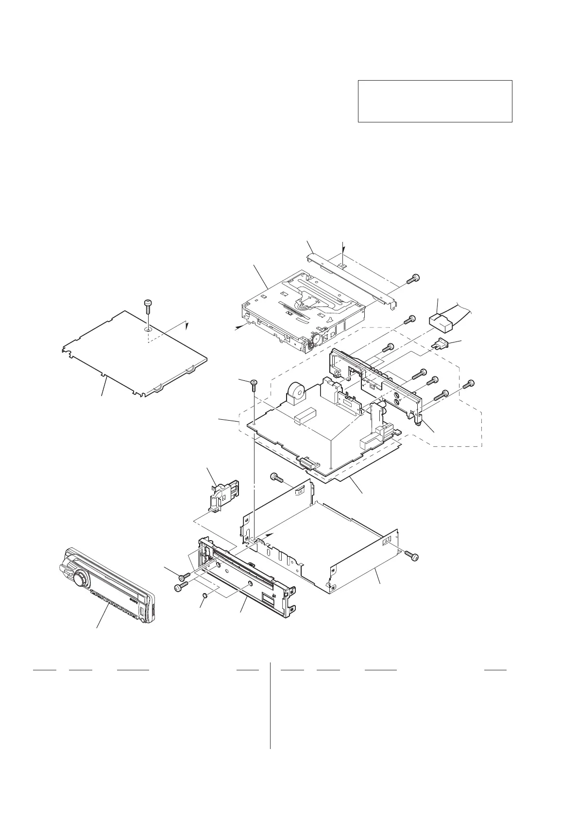
SECTION 5
EXPLODED VIEWS
1 X-2320-690-3 PANEL ASSY, SUB
2 3-042-244-11 SCREW (T)
3 X-2179-399-1 LOCK ASSY (S)
4 2-050-124-02 SCREW +BTT 2.6X5.2
5 A-1785-108-A MAIN BOARD, COMPLETE
6 1-833-974-11 CONNECTION CORD FOR AUTOMOBILE
(POWER)
FU601 1-532-877-11 FUSE (BLADE TYPE) (AUTO FUSE) 10A
#1 7-685-792-09 SCREW +PTT 2.6X6 (S)
#2 7-685-790-01 SCREW +PTT 2.6X4 (S)
#3 7-685-793-09 SCREW +PTT 2.6X8 (S)
#4 7-685-794-09 SCREW +PTT 2.6X10 (S)
#5 7-685-134-19 SCREW +P 2.6X8 TYPE2 NON-SLIT
Ref. No. Part No. Description Remark Ref. No. Part No. Description Remark
Note:
• -XX and -X mean standardized parts, so
they may have some difference from the
original one.
• Items marked “*” are not stocked since
they are seldom required for routine ser-
vice. Some delay should be anticipated
when ordering these items.
• The mechanical parts with no reference
number in the exploded views are not sup-
plied.
• Color Indication of Appearance Parts Ex-
ample:
KNOB, BALANCE (WHITE) . . . (RED)
↑ ↑
Parts Color Cabinet’s Color
• Accessories are given in the last of the
electrical parts list.
5-1. MAIN SECTION
The components identifi ed by mark 0
or dotted line with mark 0 are critical for
safety.
Replace only with part number specifi ed.
not supplied
not supplied
FU601
not supplied
front panel section
not supplied
not supplied
#1
#1
#1
#3
#4
#4
#5
#5
#3
#2
#1
A
A
B
B
1
2
3
4
6
A
5
MG-101Y-188//Q
not supplied
 Loading...