EasyManua.ls Logo

Sony CDX-MP40 User Manual

Sony CDX-MP40
66 pages
To Next Page IconTo Next Page
Page #1 background imageLoading...
Page #1 background image
1
Ver 1.1 2003. 05
Model Name Using Similar Mechanism NEW
CD Drive Mechanism Type MG-393MC-121
Optical Pick-up Name KSS-721A
SERVICE MANUAL
US Model
Canadian Model
AEP Model
UK Model
CDX-MP40
AUDIO POWER SPECIFICATIONS (US Model)
POWER OUTPUT AND TOTAL HARMONIC DISTORTION
23.2 watts per channel minimum continuous average power into
4 ohms, 4 channels driven from 20 Hz to 20 kHz with no more
than 5% total harmonic distortion.
CD player section
Signal-to-noise ratio 90 dB
Frequency response 10 – 20,000 Hz
Wow and flutter Below measurable limit
Tuner section
FM
Tuning range 87.5 – 107.9 MHz (US, Canadian Model)
87.5 – 108.0 MHz (AEP, UK Model)
Antenna terminal External antenna connector
Intermediate frequency 10.7 MHz/450 kHz
Usable sensitivity 9 dBf
Selectivity 75 dB at 400 kHz
Signal-to-noise ratio 67 dB (stereo),
69 dB (mono)
Harmonic distortion at 1 kHz
0.5% (stereo),
0.3% (mono)
Separation 35 dB at 1 kHz
Frequency response 30 – 15,000 Hz
AM (US, Canadian Model)
Tuning range 530 – 1,710 kHz
Antenna terminal External antenna connector
Intermediate frequency 10.7 MHz/450 kHz
Sensitivity 30 µV
MW/LW (AEP, UK Model)
Tuning range MW : 531 – 1,602 kHz
LW : 153 – 279 kHz
Aerial terminal External aerial connector
Intermediate frequency 10.7 MHz/450 kHz
Sensitivity MW : 30 µV
LW : 40 µV
SPECIFICATIONS
Power amplifier section
Outputs Speaker outputs
(sure seal connectors)
Speaker impedance 4 – 8 ohms
Maximum power output 52 W × 4 (at 4 ohms) (US, Canadian Model)
50 W × 4 (at 4 ohms) (AEP, UK Model)
General
Outputs Audio outputs (front/rear)
Power antenna relay control terminal
Power amplifier control terminal
Inputs Telephone ATT control terminal
BUS control input terminal
BUS audio input terminal
Remote controller input terminal
Antenna input terminal
Tone controls Low: ±10 dB at 60 Hz (XPLOD)
Mid: ±10 dB at 1 kHz (XPLOD)
High: ±10 dB at 10 kHz (XPLOD)
• The tuner and CD sections have no adjustments.
Sony Corporation
e Vehicle Company
Published by Sony Engineering Corporation
9-877-000-02
2003E04-1
© 2003. 05
– Continued on next page –
FM/AM COMPACT DISC PLAYER
US, Canadian Model
FM/MW/LW COMPACT DISC PLAYER
AEP, UK Model

Other manuals for Sony CDX-MP40

Question and Answer IconNeed help?

Do you have a question about the Sony CDX-MP40 and is the answer not in the manual?

Sony CDX-MP40 Specifications

General IconGeneral
Power Output52 watts x 4 channels
CD PlaybackYes
MP3 PlaybackYes
Radio TunerAM/FM
Aux InputYes
USB PortNo
TypeCD Receiver
Form FactorSingle DIN
Media TypeCD, CD-R, CD-RW
Supported Digital Audio StandardsMP3
Faceplate TypeDetachable
Built-In EqualizerYes
Number of Equalizer Bands3
Channels4
WMA PlaybackNo
Remote ControlYes
BluetoothNo

Summary

General Information and Specifications

Product Specifications Overview

Details technical specifications for the CD player, tuner, and amplifier sections.

Audio Power and Distortion Ratings

Specifies minimum continuous average power output and harmonic distortion levels.

Tuner and CD Player Performance Metrics

Lists tuning ranges, sensitivities, frequency responses, and distortion levels.

Amplifier Features and Tone Controls

Covers speaker impedance, maximum power output, audio outputs, and tone control ranges.

Service Notes and Handling Guidelines

Optical Pick-up and Laser Diode Handling

Provides guidelines for handling the optical pick-up block and checking laser diode emission safely.

Component Replacement and Test Disc Usage

Offers advice on chip component replacement and lists required test discs for verification.

Critical Safety Precautions

Highlights critical safety warnings regarding laser radiation and component integrity.

Section 1: General Information

Control Locations and Functions

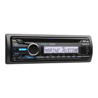
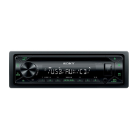
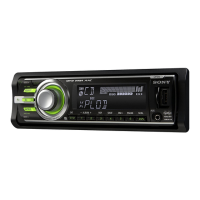
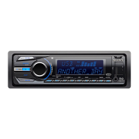
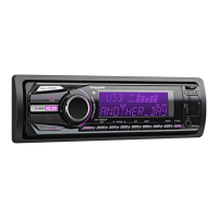
Details the layout and operation of controls for US/Canadian and AEP/UK models.

Connection Examples and Notes

Illustrates wiring connections and provides essential notes for US/Canadian models.

Section 2: Disassembly Procedures

Sub Panel and CD Mechanism Disassembly

Step-by-step guide for dismantling the sub panel and CD mechanism block.

Main Board and Heat Sink Removal

Instructions for removing the main board and heat sink components.

Lever, Servo Board, and Roller Assembly

Procedures for disassembling the lever section, servo board, and shaft roller assembly.

Floating Block and Optical Pick-up Block Removal

Instructions for safely removing the floating block and optical pick-up block.

Section 3: Diagrams and Schematics

IC Pin Descriptions

Lists pin descriptions for key integrated circuits on the servo and main boards.

Circuit Boards Location

Shows the physical layout of various circuit boards within the unit.

Block Diagrams Overview

Illustrates the functional blocks of the CD, Main, and Display sections.

CD Mechanism Schematic Diagrams

Detailed schematic diagrams specific to the CD mechanism section.

Main Section Schematic Diagrams

Comprehensive schematic diagrams covering the main unit circuitry.

IC Block Diagrams

Visual representations of the internal structure and function of key ICs.

Section 4: Exploded Views

Chassis Section Exploded View

An illustrated breakdown of the chassis and its primary mechanical components.

Front Panel Section Exploded View

Exploded diagram showing the front panel assembly and its constituent parts.

CD Mechanism Exploded Views

Detailed illustrations of the CD mechanism parts for easy identification and assembly.

Section 5: Electrical Parts List

Disc In SW, Display, and Key Board Parts

Lists components for the Disc In SW, Display, and Key boards, including semiconductors and passive components.

Main Board Electrical Components

Comprehensive listing of resistors, capacitors, ICs, and other components for the main board.

Relay, Servo, and Tuner Board Components

Details parts for the Relay, Servo, and Tuner boards, including connectors, diodes, and resistors.

Service Manual Supplement

Production Place Change Notification

Informs about a change in production origin for AEP/UK models based on serial number.

Related product manuals