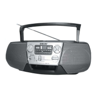
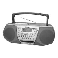
CFD-922L
– 45 – – 46 –
6-16. SCHEMATIC DIAGRAM — POWER SUPPLY SECTION —
Note on Schematic Diagram:
• All capacitors are in µF unless otherwise noted. pF: µµF
50 WV or less are not indicated except for electrolytics
and tantalums.
• C : panel designation.
• U : B+ Line.
• Total current is measured with no cassette installed.
• Power voltage is dc 9V and fed with regulated dc power
supply from battery terminal.
(Page 38)
Note: The components identified by mark 0 or dotted line
with mark 0 are critical for safety.
Replace only with part number specified.
 Loading...