Do you have a question about the Sony CFM-10 and is the answer not in the manual?
Details the various frequency bands covered by the CFM-10/10L radio receiver.
Specifies output impedance and power input voltages (AC/DC) for different regions.
Outlines power consumption in AC mode and expected battery life for recording/playback.
Provides physical dimensions and weight specifications for the unit.
Highlights critical components for safety and replacement guidelines.
Details safety checks, including AC leakage tests and measurement methods.
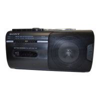
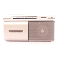
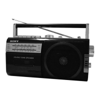
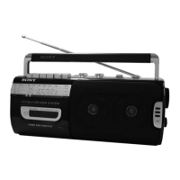
Identifies and describes the purpose of all external controls and indicators.
Step-by-step instructions for correctly setting the radio dial pointer.
Procedures for cleaning, demagnetizing, and measuring mechanical parts.
Guides for performing precise electrical alignments in the radio and cassette sections.
Illustrations showing the layout of components on the printed circuit boards.
Detailed circuit diagrams illustrating the internal electronic connections.
Diagram showing the assembly and parts of the front panel.
Diagram illustrating the assembly and parts of the rear cabinet.
Exploded view of the tape mechanism deck, part 1.
Exploded view of the tape mechanism deck, part 2.
List of primary electronic components, including semiconductors and capacitors.
Lists power transformers, cords, and related components.
Details various components like ICs, switches, connectors, and diodes.
A list of screws and fasteners used in the assembly.
Information on the change from MF-10C to MF-M10-117 tape transport mechanism.
Exploded view of the new tape mechanism deck (MF-M10-117), part 1.
Exploded view of the new tape mechanism deck (MF-M10-117), part 2.
Details the change in the main board part number for specific models.
Updated printed wiring board layout for the new main board.
Updated schematic diagram reflecting the new main board.
Updated electrical parts list for the new main board.
| Type | Portable Cassette Player |
|---|---|
| Brand | Sony |
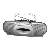
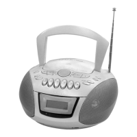
| Model | CFM-10 |
| Number of Batteries | 4 |
| Power Source | Battery |
| Features | Built-in Speaker |