– 7 –
SECTION 3
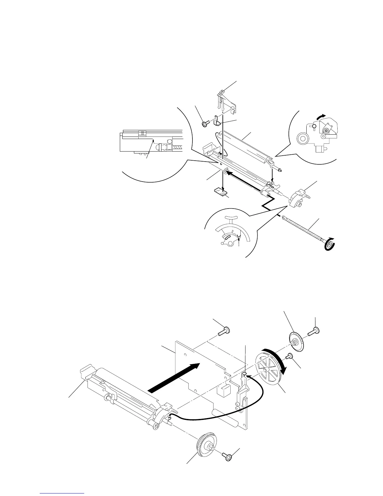
DIAL POINTER SETTING
Note : Follow the instaooation procedure in the numerical order given.
1 Attach TU worm to tuner chassis.
2 Attach needle, tighten needle spring using a bolt, then attach TU
LED board.
3 Rotate TU worm until needle stops at the stopper shown in Fig. A.
4 Mount PLATE BLIND and position it as shown in Fig. B.
5 Attach the band knob. Make sure that the projected part of the
tuner chassis fits as shown in Fig. C (the arrow).
6 Tighten idler gear, combine projected part of band knob and the
band slider so that they interlock, then mount to main board.
7 Mount VR gear to main board, then turn in the direction of the
arrow until it stops.
8 Fasten the TU gear to the TU chassis with the screw.
3
Screw (+P 2.6x5)
Retainer, Pointer
Fig. A
Fig. B
Fig. C
1
Worm, TU
5
Knob, ban
 Loading...