Do you have a question about the Sony CFM-D1 and is the answer not in the manual?
Identifies and explains the purpose of all buttons, knobs, and indicators on the device.
Details procedures for adjusting mechanical parts like heads, pinch rollers, and tape tension.
Outlines electrical alignment procedures for radio and tape sections.
Illustrates the layout of components on the printed circuit boards.
Provides the electrical circuit schematics for the device.
Details components and their assembly for the front cabinet section.
Details components and their assembly for the rear cabinet section.
Illustrates the first part of the tape mechanism components and their assembly.
Illustrates the second part of the tape mechanism components and their assembly.
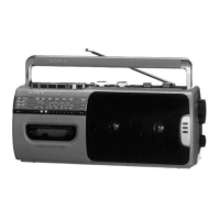
The Sony CFM-D1 is a portable radio cassette-corder designed for both audio playback and recording, featuring a dual-speaker system for enhanced sound. This device is an E Model, indicating its specific regional configuration.
The CFM-D1 serves as a versatile audio device, combining a radio receiver with a cassette player and recorder. It supports both AC power (selectable between 110-120V and 220-240V, 50/60Hz) and DC power (6V, using four R20/size D batteries), making it suitable for both home and portable use. The cassette section allows for playback and recording of audio, with a 2-track, mono recording system. The radio section offers multi-band reception, including FM, MW, SW1, and SW2, catering to a wide range of broadcast frequencies.
The CFM-D1 is designed for user-friendly operation with clearly labeled controls.
The service manual outlines specific maintenance procedures to ensure the device's longevity and optimal performance.
| Brand | Sony |
|---|---|
| Model | CFM-D1 |
| Category | Cd radio cassette-corder |
| Language | English |