EasyManua.ls Logo

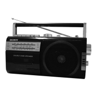
Sony CFM-S1MK2 User Manual

Sony CFM-S1MK2
24 pages
To Next Page IconTo Next Page
Page #1 background imageLoading...
Page #1 background image
CFM-S1MK2
SERVICE MANUAL
RADIO CASSETTE-CORDER
SPECIFICATIONS
E Model
Model Name Using Similar Machanism NEW
Tape Transport Mechanism Type MF-M20-117
• Frequency range
FM: Saudi Arabia: 87.6 - 107 MHz
Other models: 87.6 - 108 MHz
MW: 530 - 1 605 kHz
SW1: 2.3 - 7 MHz
SW2: 7 - 22 MHz
• Aerials FM/SW: Telescopic aerial
MW: Built-in ferrite bar aerial
• Recording system 2-track 1 channel mono
• Frequency response 80 - 8 000 Hz
• Speaker Full range: 12 cm (4
3
/
4
inches) dia., 6, cone
type (1)
• Outputs Earphones jack
For 8 impedance earphones
• Maximum power output 1.4 W
• Power requirements 110 - 120, 220 - 240 V AC
selectable, 50/60 Hz
6 V DC, 4 R20 (size D) batteries
• Power consumption AC 8 W
• Battery life
FM recording: Sony R20P: approx. 18 h
Sony alkaline LR20: approx. 50 h
Tape playback: Sony R20P: approx. 12 h
Sony alkaline LR20: approx. 30 h
• Dimensions Approx. 287 X 147 X 110 mm (w/h/d)
(11
3
/
8
X 5
7
/
8
X 4
4
/
8
inches) (incl. projecting parts)
• Mass (incl. batteries) Approx. 2 kg (4 lb. 7 oz)
• Supplied accessory Mains lead (1)
Design and specifications are subject to change without
notice.
Ver 1.1 2003.05
9-874-212-02
2003E0200-1
© 2003.05
Sony Corporation
Personal Audio Company
Published by Sony Engineering Corporation
Question and Answer IconNeed help?

Do you have a question about the Sony CFM-S1MK2 and is the answer not in the manual?

Sony CFM-S1MK2 Specifications

General IconGeneral
TypeCassette Player
Tape PlaybackYes
Tape RecordingYes
Signal-to-Noise Ratio50 dB
Headphone OutputYes
Tuner BandsFM
FeaturesBuilt-in speaker
Wow and Flutter0.25%
Speaker Output0.5W

Summary

General Information and Controls

Location and Function of Controls

Identifies the location and function of all external controls and indicators on the device.

Disassembly Procedures

Cabinet Front Assembly Disassembly

Step-by-step guide for removing the front cabinet assembly.

MD Assembly Disassembly

Instructions for disassembling the MD (MiniDisc) assembly unit.

Head, Motor, and Belt Removal

Procedure for removing the record/playback head, reel/capstan motor, and belt.

Board Component Removal

Details on removing jack, main, and fine tune boards.

Power and Battery Board Removal

Steps for disassembling battery terminal and power boards.

Installation Notes

Guidance on correct wiring installation for the device.

Dial Pointer Setting

Instructions for accurately setting the dial pointer mechanism.

Adjustment Procedures

Mechanical Adjustments

Details on mechanical adjustments, including torque and tension measurements.

Electrical Adjustments

Procedures for electrical calibration, including tape speed and azimuth.

Technical Diagrams and Schematics

Circuit Board Locations Overview

Diagram showing the physical placement of main circuit boards.

Block Diagrams

High-level functional block diagrams of the device's internal systems.

Main Section Schematic Diagrams (Part 1)

Detailed circuit schematics for the main section, covering half of the circuit.

Main Section Schematic Diagrams (Part 2)

Detailed circuit schematics for the main section, covering the second half.

Printed Wiring Board Layouts

Illustrations of the printed wiring boards showing component placement.

Integrated Circuit Block Diagrams

Functional block diagrams for key integrated circuits used in the device.

Exploded Parts Views

Front Cabinet Assembly Exploded View

Detailed parts breakdown of the front cabinet section with reference numbers.

Rear Cabinet Assembly Exploded View

Detailed parts breakdown of the rear cabinet section with reference numbers.

Mechanism Deck Section 1 Exploded View

Parts list and diagram for the first part of the mechanism deck.

Mechanism Deck Section 2 Exploded View

Parts list and diagram for the second part of the mechanism deck.

Electrical Components List

Revision History

Related product manuals