CPD-101VS
4-2
A
270 mm
B
MODE All mode
202 mm
a 1.8 mm
b 1.8 mm
a
B
A
b
B
A
A
0.24 mm
B
MODE All mode
0.30 mm
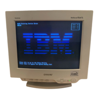
IBM AT Computer
as a Jig
1-690-391-21
1
A-1500-819-A
Interface Unit
2
*The parts above ( ) are necessary for DAS adjustment.
1
3
D-sub
(9 Pin [female])
mini Din
(8Pin)
4 Pin
3-702-691-01
Connector Attachment
3
To BUS CONNECTOR
4 Pin 4 Pin
Connect the communication cable of the computer to the connector located on the D board on the monitor. Run the service software
and then follow the instruction.
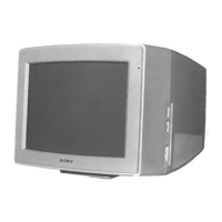
• Convergence Rough Adjustment
1. Enter the white crosshatch signal (white lines on black).
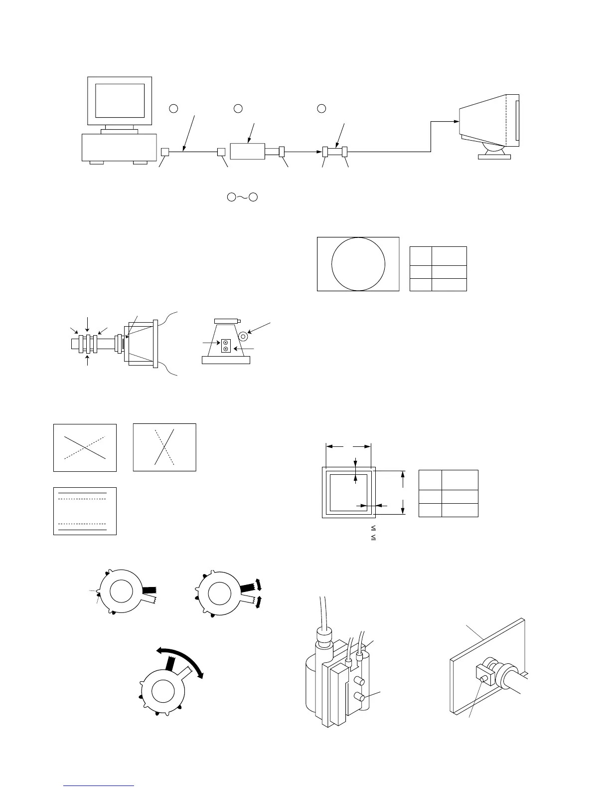
2. Adjust roughly the horizontal and vertical convergence at
four-pole magnet.
3. Adjust roughly HMC and VMC at six-pole magnet.
Standard: ± 0.1mm (In the center of screen)
• Convergence Specification
• White Balance Adjustment Specification
(1) 1100K (2) 9300K
x = 0.274 ± 0.008 x = 0.283 ± 0.008
y = 0.287 ± 0.008 y = 0.298 ± 0.008
(3) 5000K
x = 0.345 ± 0.008
y = 0.358 ± 0.008
• Vertical and Horizontal Position and Size
Specification
• Focus adjustment
Adjust the focus volume 2 for the optimum focus.
TLV
XCV
YCH
NECK Assy
Six-Pole Mg
P.S Mg
XBV
DY CRT
Four-Pole Mg
<6 Pole Magnet>
Fig. 4Fig. 3
Fig. 5
XCV YCH
B
R
TLV
RB
R
B
B
R
Fig. 1
Fig. 2
FBT
Focus volume 2
A Board
Focus (H)
Tab B
Tab A
Adjust HMC
Ad
ust VMC