CPD-101VS
4-1
SECTION 4
ADJUSTMENTS
5. Attach the sensor of the landing adjustment unit on the CRT
surface.
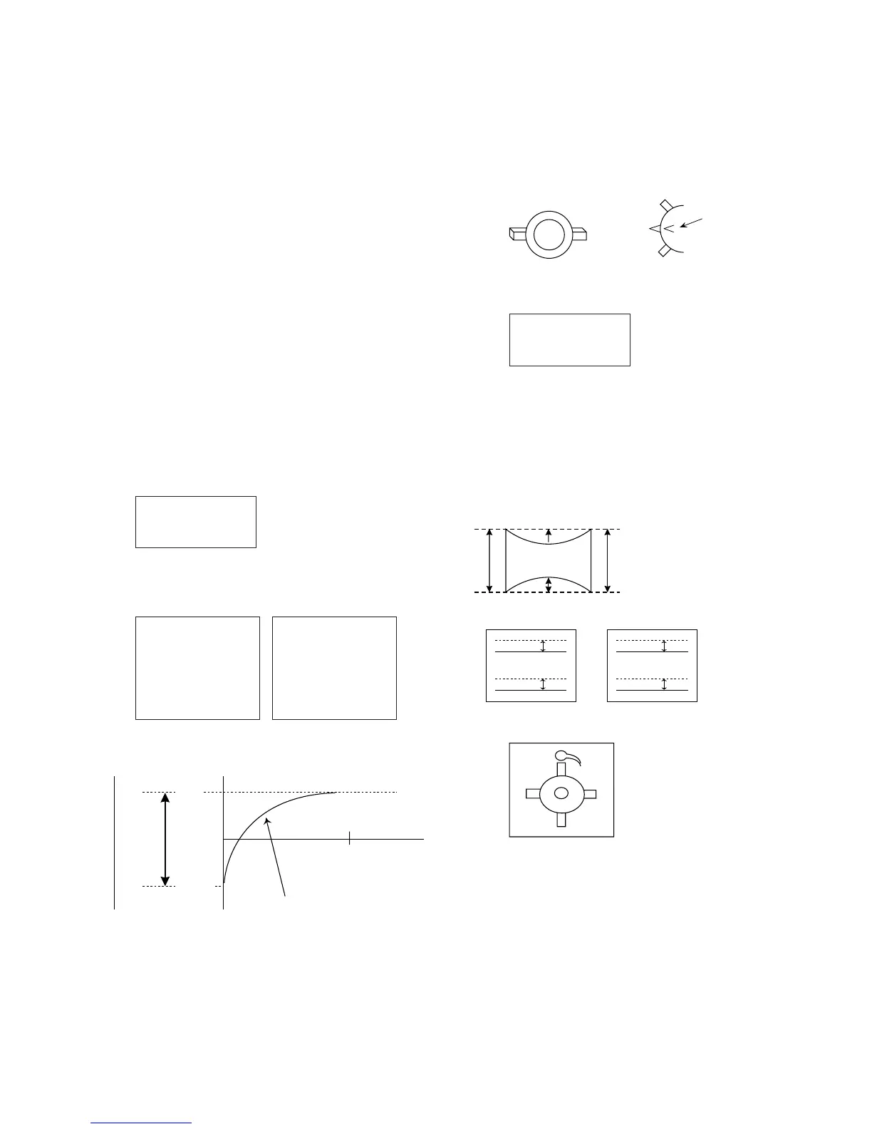
Purity magnet position
<Neck Assy Zero Position>
• Landing Rough Adjustment
1. Enter the full white signal. (or the full black dots signal)
2. Set the contrast to “CONT”=MAX.
3. Make the screen monogreen.
Note: Off the outputs from R ch and B ch of SG.
4. Reverse the DY, and adjust coarsely the purity magnet (2-
pole Mg) so that a green raster positions in the center of
screen.
5. Moving the DY forward, adjust so that an entire screen be-
comes monogreen.
6. Adjust the tilt of DY, and fix lightly with a clamp.
Note: “TILT” shall be set at 0.
• Landing Fine Adjustment
< Measurement condition >
Brightness : ∑Ik (520µA)
Magnetic field : BH=0, BV=45µT
CRT size : 270 × 202
Measurement point : 256 × 190
Temperature : 25ºC
After aging for 9 minutes and more than 3 hours, adjust so
that it is exactly this value.
a
b
cd
[ µm ]
a1 a4 a7
a2 a5 a8
a3 a6 a9
- a1 - a4 - a7
— — —
2 2 2
- a2 - a5 - a8
— — —
2 2 2
- a3 - a6 - a9
— — —
2 2 2
+ a1 + a4 + a7
— — —
222
+ a2 + a5 + a8
— — —
222
+ a3 + a6 + a9
———
222
1 minute
3 hours
< Adjustment target>
After aging for 1 minute and more than 3 hours, adjust so
that it is exactly this value.
1. Put the set inside the Helmholtz coil.
2. Input the single green signal.
3. Demagnetize the CRT surface with the hand degausser , and
perform auto degaussing.
4. Attach the wobbling coil to the designated part of the CRT
neck.
6. Adjust the DY position and purity, and the DY tilt.
7. Fasten DY with screw.
Note: Torque 22 ±2kgcm (2.2 ± 0.2 Nm)
Perform auto degaussing.
8. Adjust each top and bottom pins by two wedges, and also
adjust swinging DY neck right-left by H.TILT and horizon-
tal trapezoid, and then fix with two wedges.
(When fixing DY with wedges, insert wedges completely so
that the DY does not shake.)
“a” and “b” must be equal, and
“c” and “d” must be equal.
Signal : Inverted crosshatch (Make the monogreen)
L/D control specification
± 5 ± 7 ± 5
± 5 ± 7 ± 5
± 5 ± 7 ± 5
<How to drive in wedges>
9. If they do not satisfy the specification, connect the purity
magnet on DY and the disc magnet of the front and the rear
of DY located CRT side.
Note:
(1) When necessary to paste magnets more than 2 pieces, be
careful that the convergence and the distortion would be al-
terable.
(2) Paste within 80 to 120 mm from the DY on the diagonal line
of the magnet.
10. If using the magnet, be sure to demagnetize with the de-
gausser and check.
11. Remove the sensor and wobbling coil.
12. Check that the DY is not tilting.
B
R
B
R
A
B
R
B
R
B
A1
B1
“A” and “B”,
“A1” and “B1”
must be equal.
Set the
finger
+ ax
—
2
- ax
—
2
L/D [ µm ]
180
L/D Drift Curve
1
0
ax