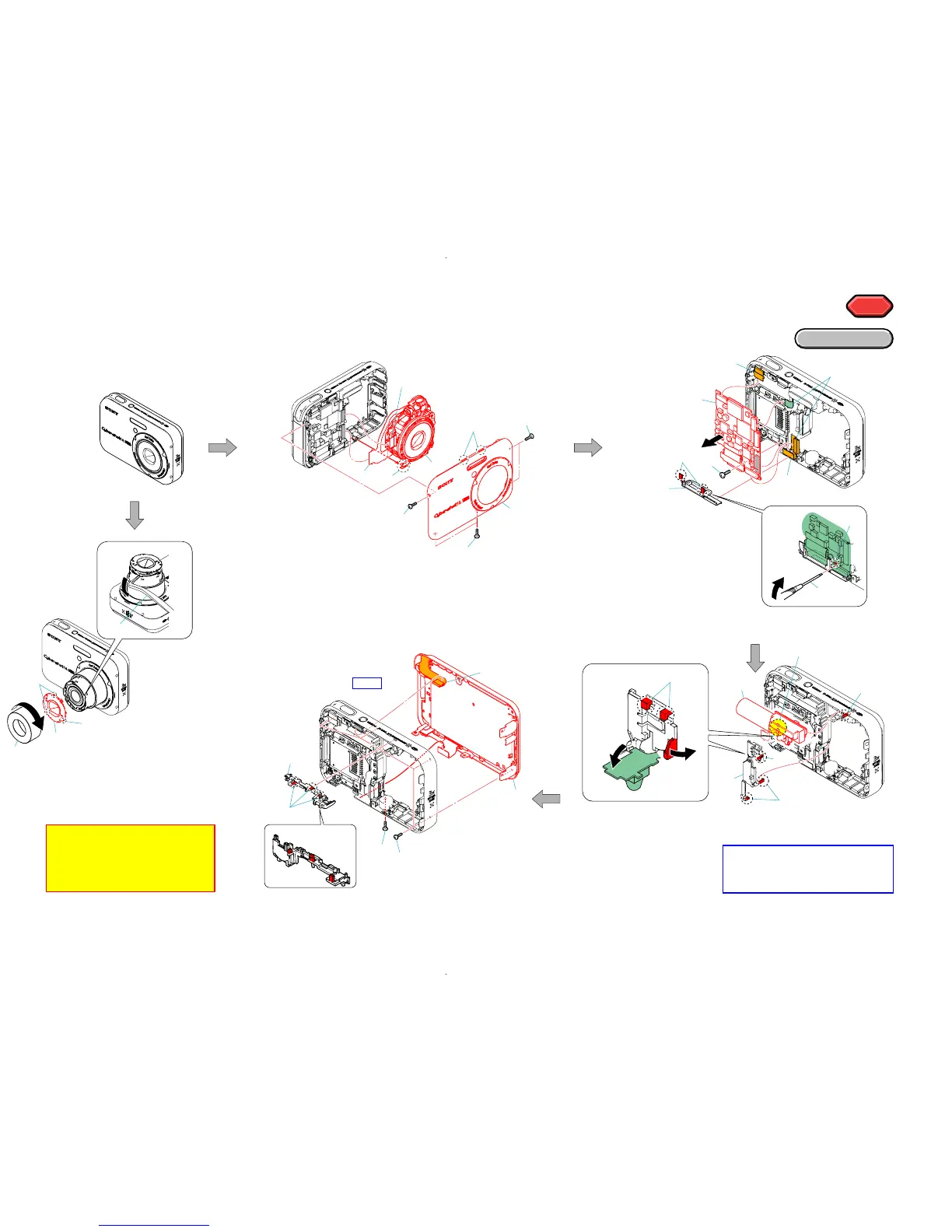
1 Flexible board
x1
2 Claw
x3
3 Microphone holder
4 #45
x1
5 #46
x4
6 Cabinet (rear) block
1 Insert the flat blade
screw driver.
2 Claw
x1
3 Claw
x2
4 Multi cap
5 Flexible board
x2
6 #46
x1
7 Remove the SY-MC board.
8 Flexible board
x2
9 SY-MC board.
1 #45
x5
2 Claw
x2
3 Cabinet (front) block
4 Flexible board
x2
5 Flexible board
x1
6 Lens block
6
5
4
4
Refer to page 2-1
" Discharging of the ST-129 flexible board's
charging capacitor (C901) ",
when discharging the capacitor.
1 Claw
x1
2 Claw
x2
3 Remove the ST board.
4 Claw
x3
5 Holder (AF)
6 Discharging the Capacitor.
1 Rotate the ornamental ring (A),
and release the bond.
2 Ornamental ring (A)
3 Insert the tweezers etc..
4 Claw
x3
5 Barrier block assembly
1
2
3
4
4
5
6
7
1
2
3
4
5
6
3
1
1
2
3
4
6
7
5
8
5
9
1
2
8
3
1
2
4
4
5
1
7 Claw
x1
8 ST board
Note: When you exchange
barrier block assembly
and ornamental ring (A), be sure
to follow the procedure carried on
"2-3. Exchange Method of Barrier
Assembly" (2-4 page).
Position of claws
(#45)
(#46)
HELP
(#45)
(#45)
(#45)
(#46)
 Loading...