2-4
DCR-SR210E/SR220/SR220D/SR220E/
HDR-SR10/SR10D/SR10E_L2
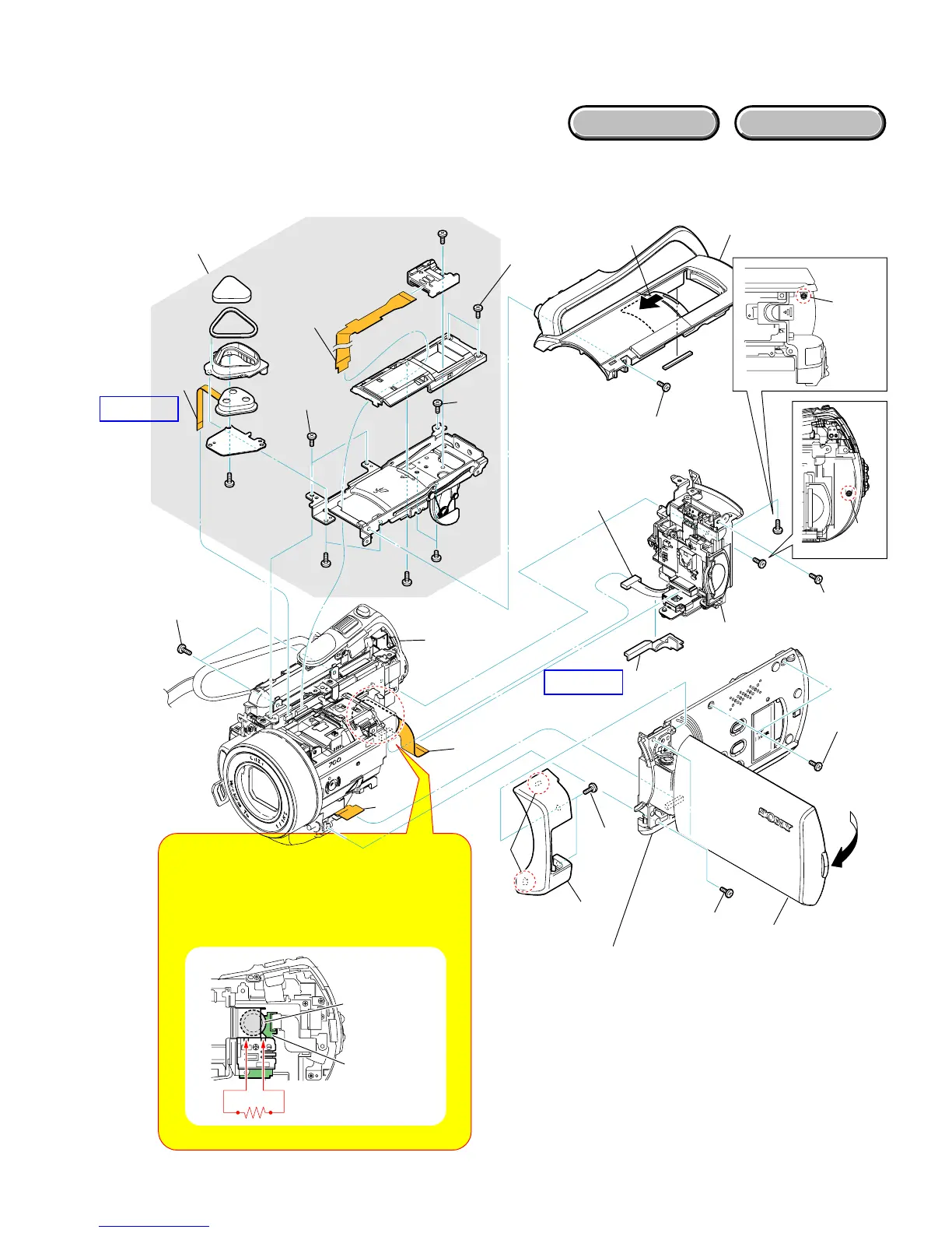
2-2-2. OVERALL SECTION-2
Follow the disassembly in the numerical order given.
1 Cabinet (R) Section (1-1 to 1-8)
2 Cabinet (Top) Block (2-1 to 2-10)
3 BT Panel Block (3-1 to 3-4)
HARDWARE LIST
3
BT Panel Block
1-2
(#1)
2-2 (#14)
2-8
(#11)
2-9
2-10
2-7
(#14)
2-6
(#2)
2-4
2-1
(#2)
3-1
(#2)
3-2
3-3
3-4
Note: High-voltage cautions
Discharging the Capacitor
Short-circuit between the two points with the short jig
about 10 seconds. To avoid the spark with the metal
plate, wrap the short jig with the insulation tape.
R:1 kΩ/1 W
(Part code: 1-215-869-11)
1
Cabinet (R)
Section
(See Page 2-9)
2
Cabinet (Top)
Block
1-1
(Open the
LCD Panel)
1-5 (#2)
1-7
(#12)
1-6
(#2)
1-4
1-8
2-3
(Open the
Shoe Cover)
2-5 (#14)
HELP02
HELP01
C5056
(Charging
Capacitor)
ST-189
Board
Overall
Section-3
(See Page 2-5)
1-3
(Claw)